Tuesday, September 2, 2025

From Specs to Sound: A DIY Guide to Designing the Perfect Sealed Speaker Enclosure

From Specs to Sound: A DIY Guide to Designing the Perfect Sealed Speaker Enclosure

From Specs to Sound: A DIY Guide to Designing the Perfect Sealed Speaker Enclosure

Introduction: The Science and Soul of Speaker Building

There is a unique and profound satisfaction that comes from creating something with your own hands, especially when that creation can fill a room with breathtaking sound. For the DIY audio enthusiast, building a custom speaker is not just a technical project; it's a journey into the heart of audio reproduction. It transforms you from a passive listener into an active creator of your own sonic experience. The sealed enclosure, often called a closed box or acoustic suspension design, stands as the perfect gateway into this rewarding world. Its elegant simplicity belies a sophisticated acoustic principle, making it an ideal and educational first project.

The fundamental purpose of any speaker enclosure is twofold. First, it must provide a stable, non-resonant housing for the speaker driver. On a basic level, the enclosure keeps all the components in one unit and holds the drivers in the correct position to work together effectively. Second, and more critically, it must solve a fundamental problem of physics known as the "acoustic short circuit." A speaker driver creates sound by moving a diaphragm back and forth. As it moves forward, it creates a positive pressure wave (sound); as it moves backward, it creates a negative pressure wave. The radiation from the rear side is in antiphase with the front side radiation. At low frequencies, where the sound waves are very long, these two opposing waves wrap around the driver and cancel each other out. The result is a dramatic attenuation of bass. The enclosure's primary job is to block this rear wave, separating it from the front wave and allowing low frequencies to propagate properly.

Why Sealed Enclosures?

Among the various types of enclosures—ported, bandpass, transmission line—the sealed design is celebrated for a distinct set of characteristics that make it highly desirable, particularly for audiophiles who prioritize accuracy and detail.

However, this performance comes with a well-understood trade-off: lower efficiency. The air spring that provides such excellent control also resists the driver's movement, meaning it requires more amplifier power to produce the same sound pressure level (SPL) as a comparable ported design. Ported enclosures are generally more efficient and allow you to use a smaller amplifier than you would need with a sealed enclosure. A sealed box will sound tight and deep, but not as loud unless you are feeding it significant power.

This guide is built on a clear premise: by understanding a few key technical specifications, you can move beyond guesswork and methodically design a sealed speaker enclosure that is acoustically optimized for your chosen driver. We will walk through a step-by-step process, transforming a list of numbers—the Thiele/Small parameters—into a blueprint for a predictable, high-quality, and deeply satisfying audio experience.

Part 1: Decoding the Driver - Understanding Key Thiele/Small Parameters

Before a single piece of wood is cut, the journey of designing a high-performance speaker enclosure begins with understanding its most critical component: the driver. A speaker driver is not just a cone that moves; it is a complex electromechanical motor with a unique set of characteristics. These characteristics are quantified by a set of specifications known as Thiele/Small (T/S) parameters, which are the essential ingredients for our design recipe.
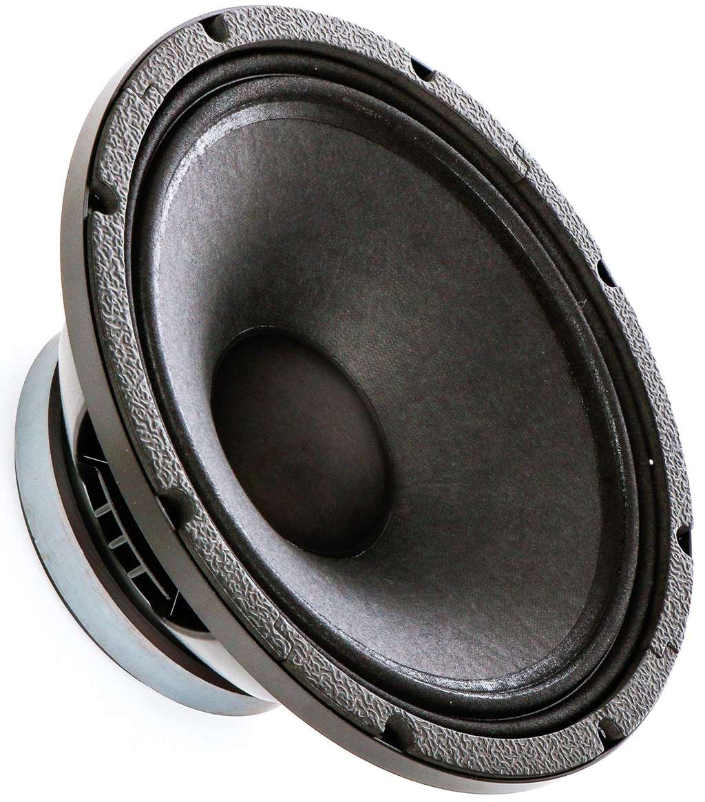
A raw woofer speaker driver
A raw woofer speaker driver, the fundamental component whose Thiele/Small parameters dictate enclosure design

What are Thiele/Small (T/S) Parameters?

Thiele/Small parameters are a set of electromechanical measurements that define the low-frequency performance of a speaker driver. Developed in the early 1970s through seminal papers presented to the Audio Engineering Society (AES) by A.N. Thiele and Richard H. Small, these parameters revolutionized loudspeaker design. Prior to their work, there were no easy or standardized methods for obtaining this data. Their research provided a framework that allows designers to accurately predict how a driver will behave when placed inside a specific enclosure, moving the process from a trial-and-error art to a predictable science.

While there are dozens of T/S parameters, for designing a sealed enclosure, we only need to focus on a critical few. These parameters describe the driver's mass, suspension stiffness, and motor strength, which together determine its acoustic output.

The "Big Three" for Sealed Enclosures

To design a sealed enclosure, you must intimately understand three primary T/S parameters provided by the driver manufacturer. These form the foundation of all our calculations.

  1. Fs (Free Air Resonance): This is the natural frequency at which the driver's moving parts (the cone, voice coil, and suspension) vibrate when suspended in free air with no enclosure. Measured in Hertz (Hz), Fs is the point where the driver moves most efficiently with the least resistance. As a general rule, a lower Fs suggests the driver has better potential for deep bass reproduction. For example, a subwoofer with an Fs of 25 Hz will typically be able to play lower notes than one with an Fs of 40 Hz. It represents the practical low-frequency limit of the driver itself.
  2. Qts (Total Q): Qts, or Total Quality Factor, is a unitless measurement that describes the driver's combined damping characteristics at its resonant frequency (Fs). It is a composite value derived from the driver's mechanical damping (Qms) and electrical damping (Qes).
    • Qms represents the mechanical control from the speaker's suspension system—the flexible surround and the spider—which act like shock absorbers.
    • Qes represents the electrical control from the motor system—the voice coil and magnet. As the coil moves through the magnetic field, it generates a counter-electromotive force (back EMF) that opposes the motion, providing electrical damping.
    The relationship is defined as 1/Qts = 1/Qes + 1/Qms. In simple terms, Qts tells you how well the driver controls its own motion. A very low Qts indicates a tightly controlled, highly damped driver, while a high Qts indicates a less controlled, more resonant driver. For sealed enclosures, a Qts value between 0.4 and 0.7 is generally considered suitable.
  3. Vas (Equivalent Compliance Volume): This parameter can be tricky to grasp, but it's crucial. Vas represents a volume of air that has the same stiffness (compliance) as the driver's own mechanical suspension. It is measured in liters or cubic feet and describes the volume of air that, when compressed, exerts the same force as the driver's suspension (Cms). A driver with a very stiff suspension will have a low Vas, while a driver with a very loose, compliant suspension will have a high Vas. This parameter is essential because it helps determine the ideal enclosure size; typically, drivers with a lower Vas are better suited for smaller enclosures.

A Quick Check: The Efficiency Bandwidth Product (EBP)

Before committing to a sealed design, a quick calculation can confirm if your chosen driver is truly a good candidate. The Efficiency Bandwidth Product (EBP) provides a strong indication of the type of enclosure a driver is best suited for. The formula is simple:

EBP = Fs / Qes

Once you calculate the EBP, you can apply a widely accepted rule of thumb:

By understanding these fundamental parameters—Fs, Qts, and Vas—and performing a quick EBP check, you have all the necessary information to move from theory to practice. You are now ready to use these ingredients to design the heart of your speaker system: the enclosure itself.

Part 2: The Blueprint - Calculating Your Enclosure Volume

With a firm grasp of the driver's key parameters, we can now transition to the most critical phase of the design process: determining the physical volume of the enclosure. This is where science meets intent. The size of the box is not arbitrary; it is precisely calculated to achieve a specific acoustic outcome. The central goal is to manipulate the driver's performance to match our desired sound character, a character defined by a single, crucial parameter: Qtc.

Step 1: Defining Your Goal - Choosing a Target Qtc

If Qts is the driver's inherent Q factor in free air, then Qtc is the total Q of the driver *after* it has been installed in a sealed enclosure. The 'c' stands for "closed box." When a driver is placed in an airtight box, the trapped air acts as an additional spring, stiffening the overall suspension. This pneumatic damping from the air inside the box contributes to the total damping of the system. As the box volume decreases, the "air spring" becomes stiffer, and the Qtc value increases. Therefore, by choosing a specific box volume, we are effectively choosing a target Qtc.

Qtc denotes the enclosure's ability to control the driver's response at resonance and is the single most important design decision you will make, as it directly dictates the bass performance, including frequency response, roll-off characteristics, and transient accuracy. The choice of Qtc is a balance between objective flatness and subjective preference.

The Spectrum of Sound: Visualizing Qtc

The relationship between Qtc and frequency response is best understood visually. The chart below illustrates how a sealed system's low-frequency output changes with different Qtc values. All curves eventually converge at higher frequencies, but their behavior in the critical bass region is dramatically different.

Here is a breakdown of what each Qtc value means for the sound you will hear:

Step 2: The Magic Formula - Calculating Net Volume (Vc)

Once you have chosen your target Qtc, you can calculate the required net internal volume of your enclosure (Vc) using a cornerstone formula of sealed box design. This formula directly links the driver's parameters to your design goal.

Vc = Vas / [ (Qtc / Qts)² - 1 ]

Let's break down the components:

  • Vc: The Net Internal Volume of the enclosure you are solving for (in the same units as Vas).
  • Vas: The Equivalent Compliance Volume of your driver (from the spec sheet).
  • Qtc: Your chosen target Q for the system (e.g., 0.707).
  • Qts: The Total Q of your driver (from the spec sheet).

Practical Application: A Worked Example

Let's design an enclosure for a hypothetical 6.5" mid-woofer with the following Thiele/Small parameters, which are similar to those found in some real-world drivers used in DIY projects :

  • Vas: 49 liters
  • Qts: 0.26
  • Fs: 30 Hz

Our goal is a maximally flat response, so we will choose a target Qtc of 0.707.

Now, we plug the values into the formula:

Vc = 49 / [ (0.707 / 0.26)² - 1 ]
Vc = 49 / [ (2.719)² - 1 ]
Vc = 49 / [ 7.393 - 1 ]
Vc = 49 / 6.393
Vc ≈ 7.66 liters

The calculation shows that to achieve our target Qtc of 0.707 with this specific driver, we need a sealed enclosure with a net internal volume of approximately 7.66 liters. While understanding this formula is empowering, for convenience, many builders use online calculators or dedicated software. Programs like BassBox Pro or free tools like WinISD can perform these calculations instantly and provide detailed graphs, but they are all built upon this fundamental mathematical relationship.

Step 3: From Net to Gross - Accounting for Real-World Volume

The calculated `Vc` (7.66 liters in our example) is the *net* internal air volume the driver requires to perform as intended. However, the physical box you build must be larger to account for the volume displaced by the components inside it. The volume occupied by the speaker driver(s), bracing materials, and any internal crossover or terminals needs to be added to the total volume calculated.
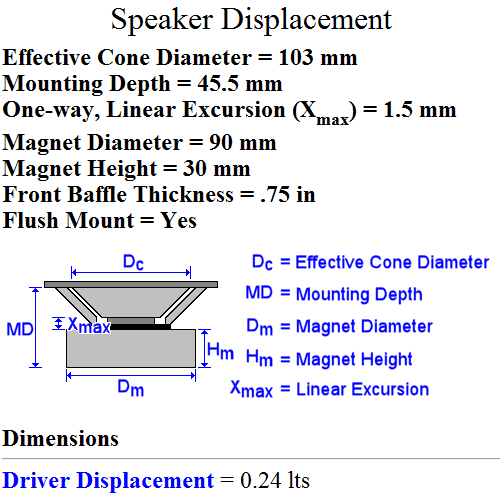
Speaker driver displacement calculation
An example of calculating driver displacement, which must be added to the net volume to find the gross enclosure volume
  • Driver Displacement: The magnet structure and basket of the driver itself take up significant space. This volume must be added to `Vc`. Manufacturers sometimes provide this value, but if not, it can be estimated. Online tools like the Driver Displacement Calculator can provide a good estimate based on the driver's physical dimensions. For a typical 6.5" driver, this might be around 0.6 liters.
  • Bracing Displacement: Internal braces are crucial for rigidity but also occupy volume. You must estimate the volume of your bracing (length x width x height for each piece) and add it to the total. For a small box, this might be 0.2 to 0.5 liters.
  • Other Components: If the crossover network and speaker terminals are mounted inside the enclosure, their volume must also be accounted for.

The final calculation for the physical box you need to build is:

Gross Box Volume = Vc + Driver Displacement + Bracing Displacement + ...

Using our example:

Gross Box Volume = 7.66 L + 0.6 L (driver) + 0.3 L (bracing) = 8.56 liters

This gross volume is the target you will use to determine the final external dimensions (Height x Width x Depth) of your speaker box, taking into account the thickness of the material you will use for construction.

Part 3: The Finishing Touch - The Art and Science of Damping

Once the enclosure volume is calculated and the box is built, there is one final, crucial step to refine its performance: the addition of internal damping material. This is often referred to as "stuffing" or "filling" the enclosure. While it may seem like a simple act of adding fluffy material, damping is a nuanced process that serves multiple acoustic purposes, transforming a good enclosure into a great one by controlling unwanted resonances and subtly altering the box's acoustic properties.

Why Add Stuffing to a Box?

The addition of damping material like polyfill, fiberglass, or wool inside a sealed enclosure has two primary and significant effects on the sound.

1. Taming Internal Reflections and Standing Waves

The primary and most intuitive goal of damping is to absorb sound energy inside the box. When the driver moves, it radiates sound not only forward into the room but also backward into the enclosure. These back waves bounce off the internal panels. Without damping, these reflections can travel back towards the speaker cone and pass through it, coloring the sound that reaches the listener. This can create audible resonance, a "boxy" or "hollow" coloration, and degrade the overall clarity, especially in the midrange frequencies. Damping material placed on the walls and within the volume of the enclosure effectively absorbs this unwanted energy, particularly at mid and high frequencies, ensuring that the sound you hear is predominantly the direct radiation from the front of the driver.

2. The "Magic" Effect: Increasing Apparent Volume

The second effect is less intuitive but profoundly important. Adding the correct amount of damping material can make the enclosure "act" acoustically larger than its physical dimensions. Stuffing can increase the effective frequency range downward because the internal sound wave is slowed, making the box seem larger to the driver. This phenomenon is due to a change in the thermodynamic process inside the box.

This reduction in pressure makes the air "spring" less stiff, which is acoustically equivalent to being in a larger box. This effect can increase the apparent or acoustical volume (Vab) by a factor (α) of up to 1.4, though a more conservative estimate is typically 15-25%. This "free" extra volume can lower the system's final resonant frequency (fc) and Qtc, resulting in deeper bass extension and a smoother frequency response.
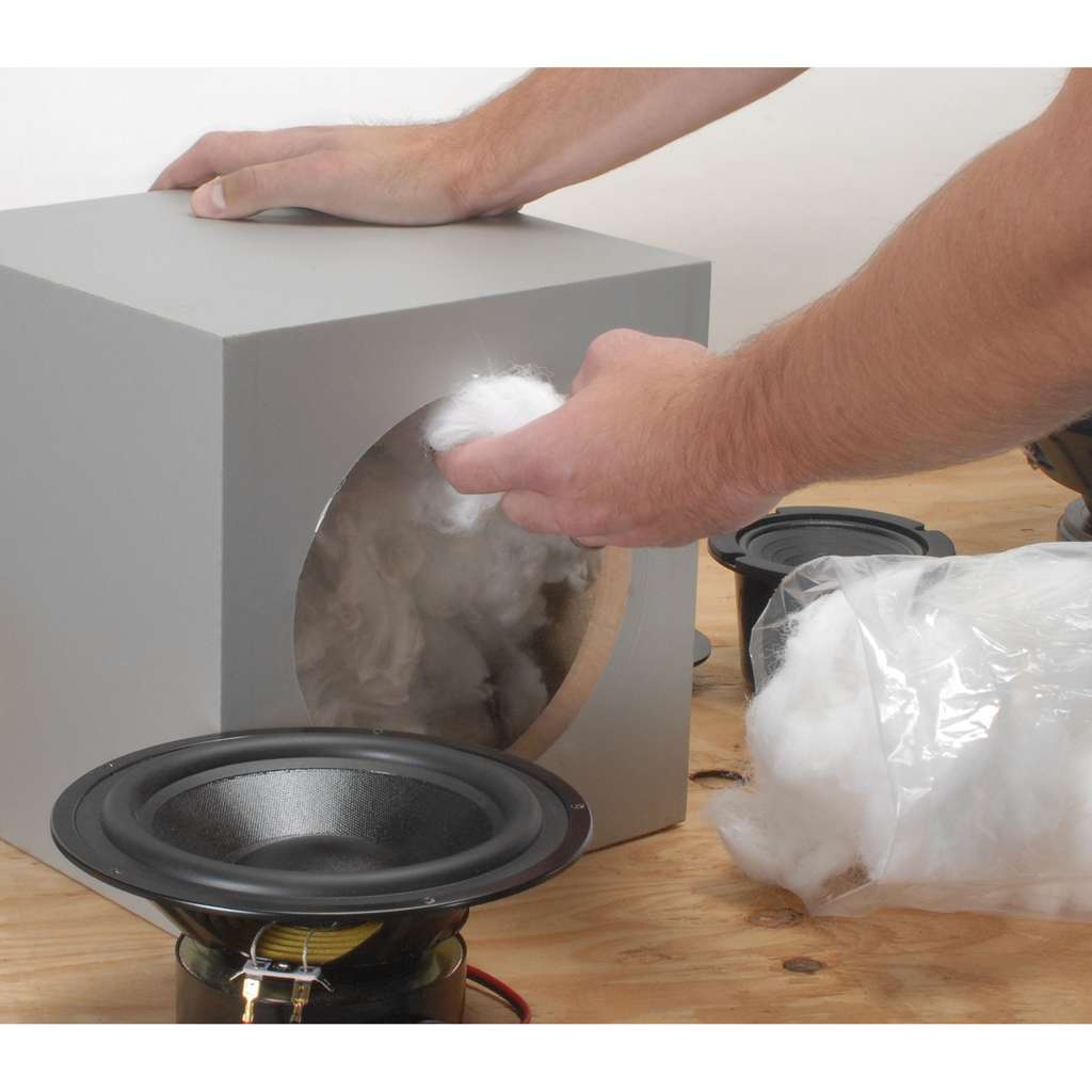
Installing acoustic damping material
Acoustic damping material, such as polyester fiberfill, is essential for controlling internal reflections and increasing the apparent volume of the enclosure

Choosing Your Damping Material

Several materials are commonly used for damping, each with its own pros and cons.

How Much is Too Much?

Finding the right amount of damping is a balancing act. There are risks associated with using both too little and too much material.

Best Practice and Guidelines

A good starting point is to aim for a specific density. A widely cited guideline is to use approximately 1.0 to 1.5 pounds of fiberfill per cubic foot of enclosure volume (or about 16-24 grams per liter). The material should be gently fluffed up and distributed evenly throughout the enclosure, leaving a small, clear space directly behind the driver's magnet to allow it to "breathe."

Ultimately, the final amount should be determined by listening. Start with the calculated amount, then add or subtract small portions of stuffing to fine-tune the response. Listen for the point where the bass is tight, defined, and articulate, without sounding overly dry or boomy. This final tuning by ear is where the "art" of speaker building complements the "science" of the design.

Part 4: Bringing It to Life - Construction Best Practices

With the design finalized, the calculations complete, and an understanding of damping in hand, it's time to turn the blueprint into a physical reality. The quality of construction is just as important as the accuracy of the design. A poorly built box can undermine even the most perfect calculations, introducing rattles, resonances, and leaks that degrade sound quality. Adhering to a few key best practices will ensure your enclosure is as solid and acoustically inert as possible.

Material Matters

The choice of material for your enclosure has a significant impact on its acoustic performance. The ideal material is dense, stiff, and well-damped, meaning it resists vibration and does not have its own strong resonant character.

Two Golden Rules for Sealed Enclosures

If you remember nothing else about construction, let it be these two principles. They are the foundation of a high-performance sealed enclosure.

1. Rigidity is King

The enclosure should be an immovable, silent partner to the driver. Any vibration in the cabinet walls is, by definition, a form of distortion. A vibrating panel becomes a secondary, uncontrolled sound source that muddies the output of the driver. Internal bracing is the most effective way to increase the rigidity of an enclosure without dramatically increasing its weight or thickness. A well-braced 3/4" MDF box will almost always outperform a thicker, unbraced box. Braces should connect opposite panels (e.g., side-to-side, top-to-bottom) to counteract the flexing forces. "Window" braces, which are panels with large cutouts, are particularly effective as they add stiffness in multiple directions while minimally impacting airflow and internal volume.
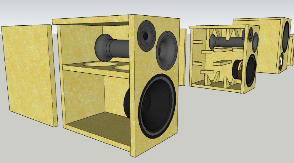
Internal bracing of a speaker cabinet
A 3D rendering showing the intricate internal bracing system of a speaker cabinet, crucial for ensuring rigidity and minimizing panel vibration

2. It MUST Be Airtight

This rule is non-negotiable for a sealed enclosure. The entire acoustic principle of the design relies on the trapped volume of air acting as a perfect spring. Any leak, no matter how small, will compromise the design. A leak turns your carefully calculated acoustic suspension system into a poorly designed, uncontrolled ported box, often resulting in audible whistling or "chuffing" noises and a complete loss of the tight, controlled bass you worked to achieve. To ensure an airtight seal:

Final Assembly

The construction process typically follows a logical sequence. First, cut all panels to their precise dimensions—remember the old adage, "measure twice, cut once."; Assemble the box panel by panel, using wood glue and clamps to ensure tight joints. Screws can be used for additional strength but are not a substitute for good glue joints. Once the main box is assembled and the glue is dry, apply the internal sealant. Install the damping material and the speaker wire terminals. Finally, solder the wires to the driver, place the driver gasket on the baffle, and screw the driver securely into place, being careful not to overtighten and strip the holes or damage the driver's frame.

Conclusion: Your First Step into High-Fidelity Sound

The journey from a set of raw specifications to a finished, high-performing loudspeaker is one of the most gratifying experiences in the world of audio. We have navigated the entire process, demystifying the science that governs the heart of any great speaker system. By following this guide, you have learned to translate the abstract language of Thiele/Small parameters into a tangible, predictable, and exceptional sonic result.

Let's recap the core stages of this journey:

  1. Understand Your Driver: We started by decoding the essential T/S parameters—Fs, Qts, and Vas—which define the driver's fundamental acoustic DNA.
  2. Choose Your Sound Goal: We established that the target Qtc is the most critical design choice, allowing you to dictate the final character of the bass, from "critically damped" accuracy (0.707) to "fun" warmth (0.8-1.0).
  3. Calculate the Volume: Using a fundamental formula, we transformed these parameters and goals into a precise net internal volume (Vc), the acoustic space your driver needs to thrive.
  4. Account for Reality: We adjusted the net volume to a gross volume by accounting for the physical displacement of the driver, bracing, and other components.
  5. Refine with Damping: We explored the art of applying internal damping material to control reflections and increase the apparent acoustic volume, fine-tuning the sound to perfection.
  6. Build with Precision: Finally, we emphasized the two golden rules of construction for a sealed enclosure: make it rigid and make it airtight.

The sealed enclosure, in its elegant simplicity, is the perfect teacher. It is forgiving of minor errors yet rewards precision and care with a sound quality that is pure, accurate, and deeply musical. It provides a natural, well-balanced bass sound that is suitable for critical listening and audiophile-grade systems. While the process is rooted in science and mathematics, the final result is an emotional one—the pride and joy of listening to music through a system you built with your own hands.

Now, the blueprint is yours. Find a driver that speaks to you, gather your tools, and begin the process. Embrace the challenge, enjoy the learning, and prepare to experience your favorite music in a way you never thought possible—through a speaker that is uniquely, wonderfully, and perfectly yours.

Reference

[5]
Definitions: Speaker Parameters - 919 Motoring
https://919motoring.com/definitions-speaker-parameters/
[6]
[PDF] Loudspeaker Parameters - Purdue College of Engineering
https://engineering.purdue.edu/ece103/LectureNotes/SRS_Loudspeaker_Parameters.pdf
[7]
[9]
What do the driver T/S parameters mean and will they help me ...
https://www.speakerplans.com/index.php?id=faq1
[10]
Designing and Building a Speaker Box Example - DIY Audio & Video
https://www.diyaudioandvideo.com/Tutorial/DesignBuildSpeakerBox/
[11]
Measuring Loudspeaker Driver Parameters - Elliott Sound Products
https://sound-au.com/tsp.htm
[12]
Audio Glossary - The DIY Audio Corner
https://diyaudiocorner.tripod.com/def.htm
[13]
Sealed enclosure explained in detail and calculator
https://audiojudgement.com/sealed-enclosure-closed-box/
[16]
Does Enclosure Thickness Affect Sound? - DioDIY
https://diodiy.com/blogs/news/thickness-of-enclosure
[17]
Building a Subwoofer Enclosure - Instructables
https://www.instructables.com/Building-A-Subwoofer/
[21]
[23]
Speaker Box Enclosure Designer / Calculator - DIY Audio & Video
https://www.diyaudioandvideo.com/Calculator/SpeakerBoxEnclosure/
[27]
Thiele / Small parameters explained with real world cases
https://audiojudgement.com/thiele-small-parameters-explained/
[28]
[31]
Loudspeaker Enclosure Design Guidelines - Elliott Sound Products
https://sound-au.com/articles/enclosures.htm
[33]
How Speakers Work: Sealed Speaker Enclosures
http://english.ioa.cas.cn/psk/201303/t20130313_99641.html
[34]
Sealed or Ported Subwoofer Enclosures - Which is Better? | MTX
https://www.mtx.com/library-vented-sealed-subwoofer-enclosures
[35]
Stuffing a speaker cab - Craig Vecchione's Live Sound & Production
https://www.harmonycentral.com/forums/topic/205794-stuffing-a-speaker-cab/

Monday, September 1, 2025

Marantz M7: The Legendary Tube Preamplifier That Defined an Era

Marantz M7: The Legendary Tube Preamplifier That Defined an Era

Marantz M7: The Legendary Tube Preamplifier That Defined an Era

Published by IWISTAO

In the pantheon of high-fidelity audio, some components are more than just electronics. They are legends, cultural touchstones that represent a perfect convergence of technology, artistry, and passion. The Marantz Model 7 is one such legend. Born in the golden age of Hi-Fi, this vacuum tube preamplifier didn't just reproduce music; it presented it with a soulfulness and authority that has captivated audiophiles for over six decades. It’s a story not just of circuits and tubes, but of a visionary founder and an unwavering commitment to musical truth.

The Architect of Sound: Saul Marantz's Vision

To understand the Model 7, one must first understand its creator, Saul B. Marantz. He was not merely an engineer; by trade, he was a talented graphic designer with a profound love for music and a keen eye for elegance and symmetry . His journey into audio began in his Kew Gardens, Queens basement after World War II, driven by a simple belief: he could do better than what was commercially available.

His first creation, the "Audio Consolette," was a preamplifier born from necessity. In the early 1950s, there was no single standard for record equalization; different labels used their own curves. The Consolette ingeniously incorporated settings for 36 different EQ curves, bringing order to the chaos . This problem-solving, user-focused philosophy became a cornerstone of the Marantz brand and set the stage for his most celebrated creation.

1958: The Birth of an Icon

The year 1958 was a pivotal moment for audio. The stereo LP had just arrived, promising a new dimension of realism. It was into this exciting new world that the Marantz Model 7 was born. It was an instant classic. A stereo preamplifier designed for the new format, it was a technical and aesthetic marvel that quickly became the heart of the most serious audio systems of the day.

The Model 7 was so successful that over its production run, more than 130,000 units were sold—a staggering figure for a high-end component that cost $385 at the time .

Its popularity was a testament to its impeccable sound quality and thoughtful design. The "Model 7C" designation, which often causes confusion, simply denoted that the unit was housed in its optional and elegant wooden case .

A Masterclass in Design and Function

An Aesthetic Statement

The Model 7 is immediately recognizable. Its brushed alloy faceplate, with a perfectly symmetrical layout of knobs and switches, is a masterwork of industrial design. Saul Marantz's background as a graphic designer is evident in every detail, from the satisfying, tactile feel of the controls to the elegant typography. The front panel didn't even bear the model number, but the simple, confident inscription: "Marantz Stereo Console" . It was designed not to be hidden in a cabinet, but to be displayed as a beautiful object in the living room.

Flexibility for the Modern Listener

Far from the minimalist preamps of later decades, the Model 7 was a control center. It offered a wealth of inputs, including two phono inputs, microphone, tape head, and, in a remarkable display of foresight, a ";TV" input—in 1958 . It featured independent bass and treble controls for each channel, high and low-pass filters, and a selector for various phono EQ curves (RIAA, Columbia, and 78), making it an incredibly versatile tool for the serious music enthusiast.

Under the Hood: The "Marantz Circuit"

The beauty of the Model 7 was more than skin deep. Its internal circuitry, based on three 12AX7 vacuum tubes per channel, was a work of engineering genius. The line stage employed a two-stage common-cathode amplifier with a negative feedback loop, followed by a cathode follower output stage . This final stage was critical, as it provided a low output impedance, allowing the M7 to drive a wide variety of power amplifiers and long cable runs without degrading the signal—a significant advantage over many of its contemporaries .

The Legendary Phono Stage

The true heart of the Model 7, and perhaps its most enduring contribution to audio design, was its phono preamplifier. This innovative three-stage circuit was so effective and musical that it quickly became known simply as "the Marantz circuit" . It provided the necessary amplification and RIAA equalization for phono cartridges with a quietness and richness that set a new benchmark for vinyl playback.

Point-to-Point Perfection

Inside an original Model 7, you won';t find a modern printed circuit board (PCB). Instead, you'll see a complex, beautiful web of hand-soldered, point-to-point wiring. This method of construction was the hallmark of high-end audio in its day, demanding immense skill and time. It's a physical manifestation of the craftsmanship and dedication to quality that defined the early Marantz era .

The Sound and Its Legacy

A Sonic Signature for the Ages

How does a preamplifier from 1958 sound by today';s standards? The answer is complex. By modern technical measurements, one can find faults; some critics point to its "wimpy" power supply or the choice of the 12AX7 tube for cathode follower duty as compromises of its era . Yet, to listen to a well-maintained Model 7 is to understand why it remains so coveted. It possesses a rich, warm, and deeply musical character. It has a "colourful string tone" and an exceptional "depth of image" that brings performances to life . It is not sterile or analytical; it is engaging, forgiving, and profoundly human.

The Clone Wars: Imitation as Flattery

The ultimate testament to the Model 7's design is its incredible longevity, not as a product, but as a template. For decades, its circuit has been one of the most frequently copied in the world of DIY audio. Countless kits and pre-built "clones" are available online, from inexpensive Chinese kits to high-end boutique offerings . This enduring popularity speaks volumes about the fundamental rightness of the original design. Even today, high-end manufacturers will state their products are "inspired by" the legendary Marantz 7 .

Conclusion: More Than a Preamp, A Cultural Artifact

The Marantz Model 7 is more than just a vintage preamplifier. It is a cultural artifact from a time when craftsmanship was paramount and innovation was driven by a genuine passion for music. It represents the vision of Saul Marantz, a man who fused artistry with technology to create something both beautiful and brilliant.

Whether you are lucky enough to own an original, have built a clone, or simply admire it from afar, the Model 7's influence is undeniable. Its warm, glowing tubes and satisfying controls are a reminder of a time when listening to music was an event, an experience to be savored. Its legacy continues to play on, clear and true, a perfectly tuned note in a world of static .

Wednesday, August 27, 2025

The Heart of Harmony: A Deep Dive into Push-Pull Output Transformers

The Heart of Harmony: A Deep Dive into Push-Pull Output Transformers

The Heart of Harmony: A Deep Dive into Push-Pull Output Transformers

Published on August 27, 2025

In the glowing world of tube amplifiers, the vacuum tubes themselves often steal the spotlight. But behind these glass bottles of fire lies an unsung hero, a dense block of iron and copper that does the real heavy lifting: the output transformer. And in the realm of power and clarity, the push-pull output transformer reigns supreme. It’s a masterpiece of balance, a critical component that defines an amp's voice, from the gentlest whisper to the most thunderous roar.

The Indispensable Bridge: Why Transformers?

At its core, a tube amplifier's job is to take a tiny signal and make it powerful enough to move a speaker. The problem? Tubes and speakers speak different languages. Tubes operate at high voltages with low current, while speakers are low-impedance devices craving high current. The output transformer (OPT) is the universal translator. As described in audio engineering resources, its primary function is to match the high impedance of the tubes to the low impedance of the speaker, ensuring maximum power transfer. It steps down the voltage while stepping up the current, making the tube's effort audible and preventing the kind of impedance mismatch that would cripple performance.

A Symphony of Symmetry: The Push-Pull Principle

The term 'push-pull' isn't just a catchy name; it's a literal description of how the amplifier works. A push-pull stage uses a pair of tubes (or multiple pairs) that work in opposition. One tube amplifies the positive half of the audio wave ("pushing"), while the other amplifies the negative half ("pulling"). The magic happens in the output transformer, which is specially designed with a center-tapped primary winding. The two amplified halves of the signal are fed into opposite sides of this winding and are then magnetically recombined into a complete, powerful wave in the secondary winding connected to the speaker. This design allows for greater output power and efficiency than a single-ended design using the same tubes.

A push-pull transformer is an exercise in elegant cancellation, turning opposing forces into a unified, powerful whole.

The Great Divide: Push-Pull vs. Single-Ended

Here lies the most fundamental difference between a push-pull OPT and its single-ended (SE) cousin. In an SE amp, a single tube handles the entire signal, meaning a constant DC current is always flowing through the transformer's primary winding. This DC current wants to permanently magnetize the transformer's core, a disastrous state called saturation. To prevent this, SE transformers must be built with a small air gap in their core, which makes them large, heavy, and often expensive. Push-pull circuits, by their very nature, solve this problem elegantly. Because the DC currents from the two tubes flow in opposite directions from the center-tap, their magnetic fields cancel each other out. With no net DC magnetization, the core doesn't need a gap, allowing it to be more compact and efficient. This is why you can't just use a push-pull transformer in an SE amplifier—it would saturate almost instantly.

The Sound of Symmetry: How Push-Pull OPTs Shape Tone

This symmetrical design has profound sonic implications. One of the most celebrated benefits of a push-pull stage is its inherent cancellation of even-order harmonic distortion. As explained by The Valve Wizard, a perfectly balanced push-pull stage cancels all even harmonics generated within it. This is a key reason why push-pull amplifiers are known for their clarity, low distortion, and high fidelity, making them a staple in powerful Hi-Fi systems and guitar amps where headroom is desired. While SE amps are often cherished for their "warm" and musically pleasing even-order harmonics, push-pull amps deliver a more accurate, powerful, and dynamic representation of the original signal.

The Anatomy of Quality: What Makes a Great Push-Pull OPT?

But not all push-pull transformers are created equal. The difference between budget "iron" and a high-end one can be staggering, and it comes down to materials and craftsmanship.

The Core

The heart of the transformer is its core. While standard silicon steel is common, premium transformers may use exotic amorphous or nanocrystalline cores which offer lower energy loss and superior performance, especially at frequency extremes. These advanced materials contribute to greater efficiency and a cleaner sound by allowing the magnetic field to change direction with less resistance.

The Windings

How the copper wires are wound is an art form. Complex interleaving patterns—layering the primary and secondary windings—reduce leakage inductance and parasitic capacitance. This directly translates to a wider frequency response and better transient detail. Poor winding can limit high frequencies and introduce distortion, smearing the fine details in your music.

The Balance

For the push-pull magic to work, the two halves of the primary winding must be as close to identical as possible. Any imbalance in resistance or number of turns will compromise the cancellation of distortion and hum, undermining the very principle of the design. Precision is paramount, and top-tier manufacturers go to great lengths to ensure this symmetry.

The Final Word

So, the next time you admire the warm glow of a tube amp, spare a thought for the silent, heavy partner sitting alongside them. The push-pull output transformer is more than just an impedance-matching device; it is an elegant piece of engineering that enables the power, clarity, and low distortion that have defined high-performance audio for decades. It is the heart of harmony, the crucial link that turns the delicate dance of electrons in a vacuum tube into the powerful, moving sound that fills a room.

Reference

[1]
THE SECRET OF SELECTING A GOOD OUTPUT TRANSFORMER
https://www.audio-talk.co.uk/fiultra/KISS%20117%20by%20Andre%20Jute.htm
[2]
[PDF] Why push-pull ? An amplifier with push-pull circuit consists of a ...
https://gzhls.at/blob/ldb/2/c/9/2/6417e92ad4ef7e13f881f1715344d0e5862e.pdf
[3]
Push-Pull Power Output Stage - The Valve Wizard
https://valvewizard.co.uk/pp.html
[4]
Types of Cores Used in Toroidal Transformers - Winding Machine
https://www.grwinding.com/types-of-cores-used-in-toroidal-transformers/

Friday, August 22, 2025

Building a Vintage Sound Power Amp with the 3AD56B Germanium Transistor

Building a Vintage Sound Power Amp with the 3AD56B Germanium Transistor

Building a Vintage Sound Power Amp with the 3AD56B Germanium Transistor

Introduction: The Allure of Germanium

In the world of audio electronics, few components evoke as much mystique and debate as the germanium transistor. Born in the pioneering days of solid-state technology at Bell Labs in 1947, germanium was the material that powered the first generation of transistor radios, computers, and audio amplifiers. Though largely superseded by silicon since the 1960s due to silicon's superior thermal stability and consistency, germanium has refused to fade away. Instead, it has cultivated a legendary status, particularly among audio purists and guitarists, for its supposedly "warmer" and more "musical" sound.

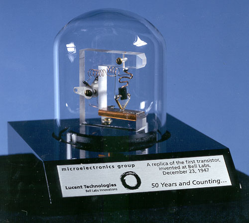
Replica of the first transistor
A replica of the first point-contact transistor, invented at Bell Labs in 1947, marking the dawn of the solid-state era

This blog post dives into a specific and rather uncommon piece of this history: the 3AD56B, a high-power Chinese germanium transistor. Unlike the low-power transistors found in vintage fuzz pedals, the 3AD56B is a workhorse capable of driving speakers. We'll explore its characteristics, compare it to its silicon counterparts, and outline the design considerations for building a unique audio power amplifier that channels the spirit of the germanium era.

Understanding the 3AD56B: A Closer Look

The 3AD56B is a PNP germanium power transistor that stands out in a field dominated by low-power signal devices. While documentation can be sparse, data from DIY electronics forums and datasheets provides a solid picture of its capabilities. It was designed for audio frequency power amplification, making it an ideal candidate for a retro-style hi-fi or instrument amplifier project.

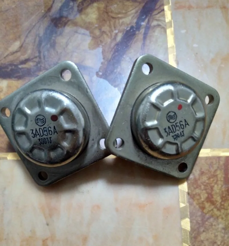
3AD56A Germanium Transistors
The 3AD56 series of high-power germanium transistors, ready for an audio amplifier project

Here are its key specifications, compiled from various sources:

Parameter Value Source
Type PNP Germanium DIYstompboxes.com
Max Power Dissipation (Pc) 50 W DIYstompboxes.com
Max Collector Current (Ic) 15 A Scribd Datasheet
Max Collector-Emitter Voltage (Vce) 45 V DIYstompboxes.com
DC Current Gain (hFE) 20 ~ 140 Scribd Datasheet
Transition Frequency (Ft) ≥ 3 KHz DIYstompboxes.com

These numbers reveal a transistor with significant power handling but a low frequency response, typical for early power germanium devices. The wide range of hFE (gain) is also characteristic, highlighting the manufacturing inconsistencies of the era and underscoring the importance of testing and matching components for any serious build.

Germanium vs. Silicon: Why Choose Germanium for an Amplifier?

The decision to use germanium over silicon is rarely about achieving technical perfection. Modern silicon transistors outperform germanium in almost every measurable way: they are more stable, more efficient, have higher gain, and are far cheaper. The choice, therefore, is about sonic character.

The Sonic Signature: Warmth and Organic Clipping

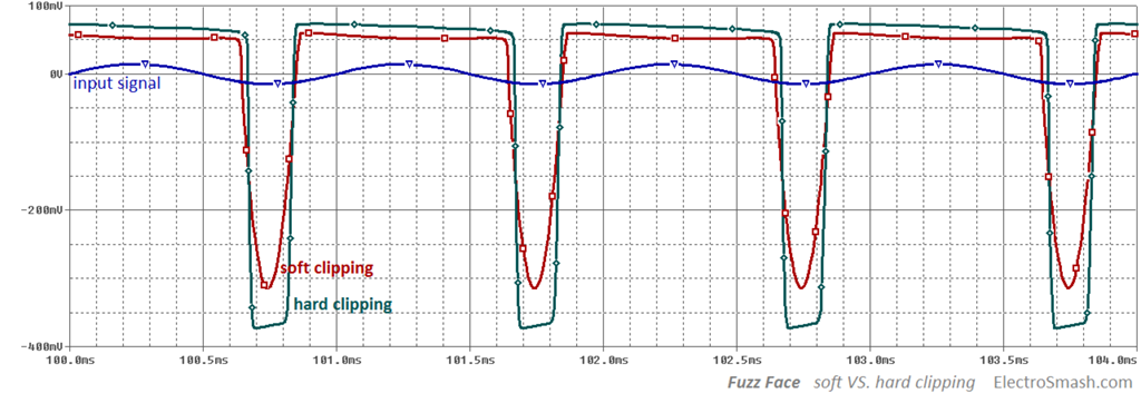
The "magic" of germanium is often attributed to its imperfections. When a transistor amplifier is pushed into distortion (clipping), the way it behaves defines its sound. Germanium has a lower forward voltage drop (around 0.3V) compared to silicon (around 0.7V), meaning it begins to clip earlier and more gradually. This creates what many describe as a "softer," "smoother," and more "organic" distortion, often compared to the natural breakup of a vacuum tube.

"Overall, when people are describing germanium transistor clipping, they often use the term 'organic.' Germanium transistor clipping, at least to me, often sounds tighter and less crunchy. All in all, it’s more akin to the natural breakup of a vacuum tube." - Crazy Chicken Guitar Pedals
Waveform showing soft vs hard clipping
A waveform comparison showing how soft clipping (red) gently rounds the signal peaks, typical of germanium, versus the sharper hard clipping (green) of silicon. Image courtesy of ElectroSmash

In contrast, silicon's sharper clipping "knee" results in a more aggressive, "harsher" distortion with more high-frequency harmonics. While this is desirable for modern high-gain sounds, the smoother onset of germanium distortion is what gives it the "vintage" warmth that builders of audio amplifiers often seek.

The Technical Trade-offs: Heat, Leakage, and Inconsistency

Working with germanium is not without its challenges. The two most significant are temperature sensitivity and leakage current.

  • Temperature Sensitivity: Germanium transistors are notoriously sensitive to heat. As they warm up, their characteristics change, which can lead to a dangerous feedback loop called "thermal runaway" where increasing temperature causes more current to flow, which in turn generates more heat. This makes proper heatsinking and bias circuit design absolutely critical.
  • Leakage Current: Compared to silicon, germanium transistors "leak" a significant amount of current even when they are supposed to be "off." This leakage is also temperature-dependent and must be accounted for in the circuit design, particularly in the biasing network.

These "flaws" are precisely why the electronics industry moved to silicon. However, for the DIY enthusiast, overcoming these challenges is part of the appeal, leading to a final product with a unique and tangible character.

Designing the Amplifier: Circuit Topologies for the 3AD56B

Building a power amplifier with the 3AD56B requires a thoughtful approach to circuit design. Given its characteristics, simply dropping it into a modern silicon-based schematic won't work. We must look to classic designs or clever hybrid solutions.

The Push-Pull Approach

For any power amplifier, a push-pull output stage is the standard. In this configuration, one transistor (or set of transistors) handles the positive half of the audio waveform, while another handles the negative half. This dramatically increases efficiency and power output compared to a single-ended (Class A) design and helps cancel out even-order harmonic distortion.

Quasi-Complementary OCL: The Classic Germanium Solution

The biggest challenge in the germanium era was creating matched pairs of complementary (PNP and NPN) power transistors. It was far easier to produce high-power transistors of a single polarity. This led to the development of the quasi-complementary circuit.

This clever design uses two identical polarity power transistors (like two 3AD56B PNPs) for the output stage, driven by a lower-power complementary pair of driver transistors. Online sellers of 3AD56B-based amplifier kits often mention using a "non-complementary same-polarity symmetrical OCL circuit," which is a direct reference to this topology (as seen on AliExpress). This is arguably the most "authentic" way to build a power amp with these devices.

A Hybrid Alternative: Modern Drivers for a Vintage Core

A more practical and stable approach is to build a hybrid amplifier. This design uses modern, reliable silicon transistors for the input and driver stages, taking advantage of their stability and high gain, while reserving the germanium 3AD56B transistors for the final output stage where their sonic character can shine through. This gives you the best of both worlds: the reliable performance of silicon and the vintage tone of germanium.

Some DIY builders have successfully adapted well-known silicon amplifier schematics by modifying the output stage for high-power germanium transistors, often using silicon drivers like the BD139/BD140 pair to provide a strong signal to the germanium finals (diyAudio Forum Discussion).

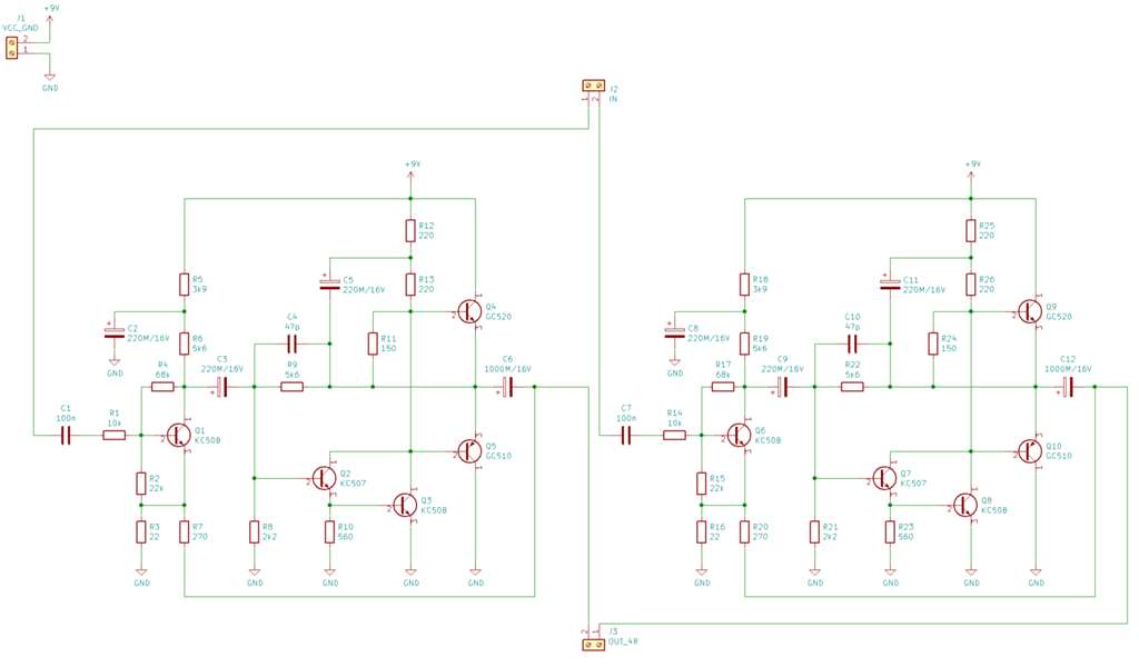
Schematic of a hybrid Germanium/Silicon amplifier
An example of a hybrid amplifier schematic, using silicon transistors for the input/driver stages and germanium transistors for the output. Source: MekWeb

Key Build Considerations: Taming the Germanium Beast

Regardless of the chosen topology, a successful build hinges on addressing germanium's inherent quirks.

Heatsinking is Non-Negotiable

The 3AD56B is rated for 50W of power dissipation. This power is converted almost entirely into heat. Without adequate heatsinking, the transistor will quickly overheat and destroy itself. A large, finned aluminum heatsink is essential for each output transistor to dissipate this heat and maintain a safe operating temperature, preventing thermal runaway.

Biasing for Stability and Sound

Biasing sets the idle (quiescent) current for the output transistors. Too little current causes "crossover distortion," a harsh sound that occurs as the signal crosses from the positive to the negative transistor. Too much current causes the transistors to run hot, waste power, and risk thermal runaway. The challenge with germanium is that the ideal bias point shifts with temperature. A classic solution is to use a germanium diode as part of the bias network, physically mounted on the same heatsink as the output transistors. As the transistors heat up, the diode heats up too, and its voltage drop changes in a way that counteracts the transistor's tendency to draw more current, thus stabilizing the bias (Vintage Radio Forum).

Component Selection and Matching

As noted, germanium transistors from the same batch can have widely varying gain (hFE). For a push-pull stage to work symmetrically and minimize distortion, it's crucial that the output transistors are a matched pair. This means buying more transistors than you need and using a multimeter with a transistor testing function (or a dedicated component tester) to find two with hFE values as close as possible.

Conclusion: Is It Worth the Hype?

Building an amplifier with the 3AD56B germanium transistor is not a project for the faint of heart, nor is it a path to achieving sterile, high-fidelity perfection. It is a journey into the heart of vintage audio technology, with all its challenges and charms. The process demands patience, careful component selection, and a solid understanding of the principles needed to tame these temperature-sensitive devices.

The reward is not found on a spec sheet. It's found in the unique sonic character—the smooth clipping, the organic warmth, and the satisfaction of creating a piece of audio equipment that sounds distinct from anything built with modern components. For the DIY audio enthusiast looking for a project that is both a technical challenge and a nostalgic exploration, breathing life into the 3AD56B is an adventure well worth taking. It's less about hype and more about heritage.

Saturday, August 16, 2025

The Allure of the Hyperbolic Horn: A Deep Dive into Acoustic Excellence

The Allure of the Hyperbolic Horn: A Deep Dive into Acoustic Excellence

The Allure of the Hyperbolic Horn: A Deep Dive into Acoustic Excellence

In the world of high-fidelity audio, few designs are as visually striking or acoustically debated as the horn loudspeaker. Among its various forms, the hyperbolic horn stands out as a pinnacle of acoustic engineering—a design that marries complex mathematics with the pure physics of sound. This article explores the history, theory, and unique characteristics of hyperbolic horns, particularly those crafted from wood, to understand why they command such reverence among audiophiles.

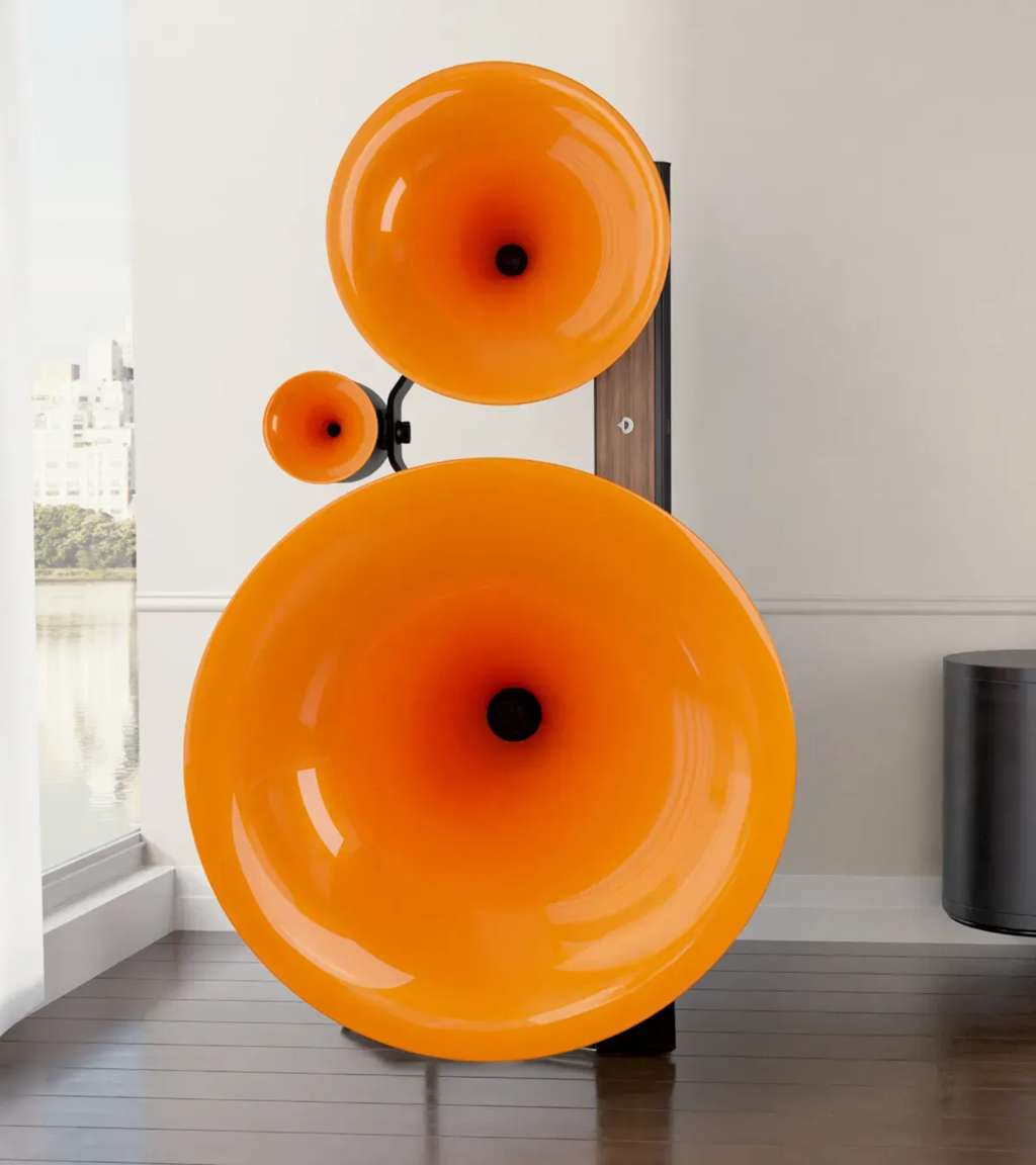
Modern horn speaker system
A modern Avantgarde Acoustic Trio horn speaker system in a contemporary living space

From Megaphones to High Fidelity: The Evolution of Horn Loudspeakers

The principle of the horn is ancient, originating with simple megaphones used to amplify the human voice. At its core, a horn is an acoustic transformer. It efficiently matches the high acoustic impedance of a sound source (like a speaker driver's diaphragm) to the low acoustic impedance of the surrounding air. This impedance matching allows for a much more efficient transfer of energy, resulting in higher sound pressure levels from less power—a key reason for their high sensitivity.

The journey of the horn into high-fidelity audio began in the early 20th century. Early phonographs relied on purely acoustic horns to make recorded music audible. With the advent of electronic amplification in the 1930s, companies like Western Electric and later Altec Lansing pioneered horn-loaded speaker systems for large movie theaters. These systems, such as the iconic "Voice of the Theatre" (VOTT), were renowned for their ability to produce concert-level volumes with exceptional clarity and dynamics, cementing the horn's place in professional audio.

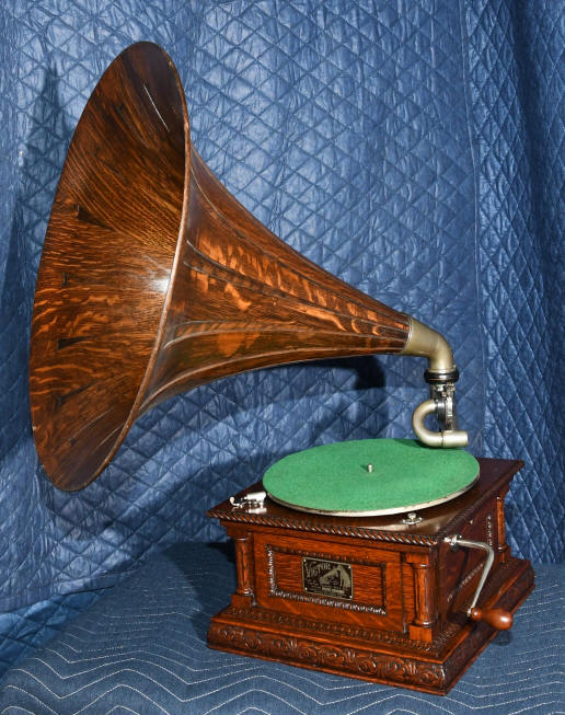
Vintage Victrola phonograph
A vintage Victrola phonograph with its characteristic wooden horn, showcasing the early application of horn technology

What Makes a Horn "Hyperbolic"?

While all horns serve the same basic function, their performance is dictated by their geometry—the specific curve or "flare rate" at which their cross-sectional area expands from the narrow throat to the wide mouth. The most common types include:

  • Conical: A simple, straight-sided flare like a megaphone. It offers good directivity control but can suffer from higher distortion.
  • Exponential: The area expands at an exponential rate. This design is known for a smooth frequency response and low distortion.
  • Tractrix: A mathematically derived curve that aims to balance the properties of conical and exponential horns.

The hyperbolic horn, also known as a "hypex" horn, is an advanced design that attempts to synthesize the best qualities of the others. Its flare rate is governed by a hyperbolic cosine function. According to a detailed analysis in Hyperbolic Horn Physics and Design, the area (A) at any distance (z) along the horn's axis is described by the equation:

A = At(cosh(z/z0) + T sinh(z/z0))2

Here, At is the throat area, z0 is a flaring constant, and T is the crucial "family parameter" that defines the horn's specific shape and acoustic behavior.

The Magic of the 'T' Parameter

The 'T' parameter is what gives the hyperbolic horn its remarkable flexibility. By adjusting its value, a designer can fine-tune the horn's performance, especially at the critical low-frequency end of its range, near the "cutoff frequency." Below this frequency, the horn no longer effectively loads the driver.

  • If T = 1, the equation simplifies to that of a pure exponential horn.
  • If T > 1, the horn's shape becomes progressively closer to a conical horn.
  • The range of 0 ≤ T < 1 is of particular interest to designers. In this range, the horn is often called a hyperbolic cosine or "cosh" horn.

A key problem with standard exponential horns is that their acoustic impedance (and thus their frequency response) begins to roll off too far above the cutoff frequency. By setting T to a value less than 1 (e.g., between 0.5 and 0.7), a designer can counteract this. As documented in studies by audioXpress and demonstrated in practical designs, a hyperbolic horn with an optimized T-value can actually create a slight rise in impedance just before the cutoff frequency. This gentle "peak" helps to maintain a strong bass response down to the absolute limit of the horn's design, resulting in a more extended and powerful low-end performance compared to its exponential counterpart.

The Art and Science of Crafting a Wooden Hyperbolic Horn

The theoretical advantages of the hyperbolic horn come at a price: they are notoriously difficult and expensive to manufacture (EngineeryourSound). Achieving the precise, continuously changing flare rate requires immense skill and precision. Unlike a simple cone, the hyperbolic curve cannot be easily formed.

For wooden horns, this often involves advanced techniques. Some artisans use CNC (Computer Numerically Controlled) machinery to carve the complex shapes from solid blocks of wood or to cut precise layers that are then stacked and smoothed. One detailed DIY project documented the process of using custom software to calculate the exact cross-sectional area at quarter-inch intervals, then creating inserts and molds from polyester resin to correct the shape of a more easily constructed square horn to perfectly match the hyperbolic curve. This highlights the dedication required to realize the design accurately.

The choice of wood is not merely aesthetic. Different woods have varying densities and damping characteristics that can subtly influence the final sound, adding a layer of warmth and naturalness that materials like metal or plastic may lack. The craftsmanship involved makes each wooden hyperbolic horn a unique piece of functional art.

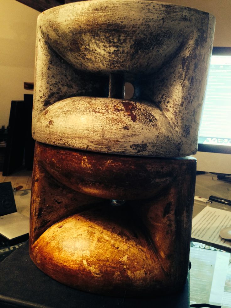
Handcrafted wooden hyperbolic horn speakers
Stacked, cylindrical hyperbolic horn speakers crafted from wood, showcasing a rustic, handcrafted aesthetic

Performance and Sonic Signature: Why Choose Hyperbolic?

The primary reason to choose a hyperbolic horn is its superior acoustic performance, particularly in the low frequencies. The design offers a unique combination of benefits:

  • High Efficiency: Like all horns, they produce high volume levels with very little amplifier power, leading to a dynamic and effortless sound.
  • Extended Low-Frequency Response: The optimized flare provides better acoustic loading near the cutoff frequency, resulting in deeper and more authoritative bass than other horn types of similar size.
  • Low Distortion: The smooth, calculated transition from throat to mouth minimizes reflections and turbulence within the horn, contributing to a clean and clear sound.

This unique performance profile has not gone unnoticed by researchers. As early as the 1960s, NASA's Jet Propulsion Laboratory (JPL) conducted in-depth studies on hyperbolic horns. A 1967 technical report, "Acoustic Spectrum Shaping Utilizing Finite Hyperbolic Horn Theory," detailed their use in creating precisely controlled, high-intensity sound fields for environmental testing of spacecraft. The research confirmed the horn's "unique property of a resonant response characteristic at frequencies just above their cutoff frequency," the very trait audiophiles cherish for bass reproduction.

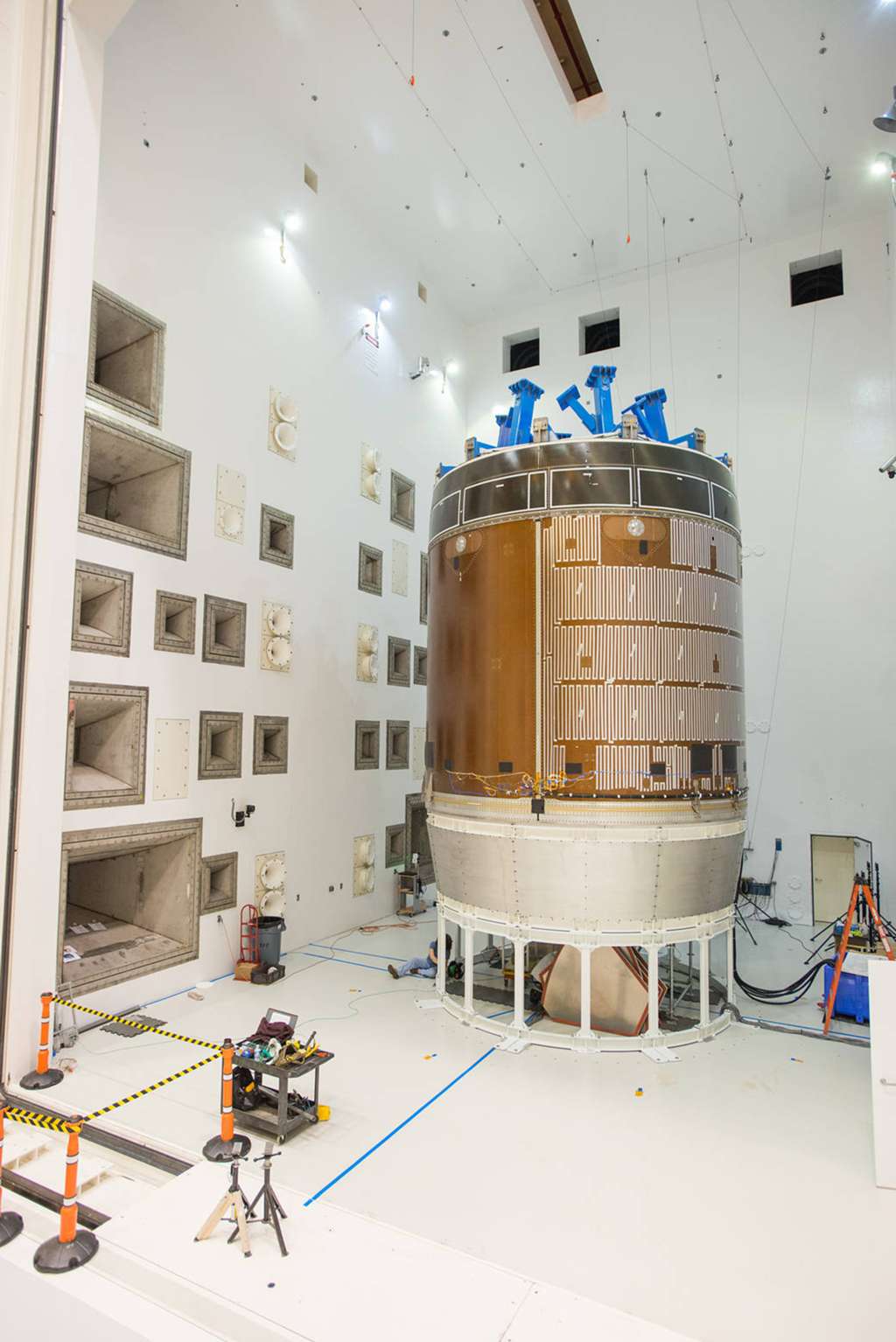
Acoustic testing facility with horn array
A large indoor testing facility featuring a wall array of acoustic horns, similar to those studied by NASA for high-intensity sound simulation

Conclusion: The Enduring Appeal of a Complex Curve

The hyperbolic horn is more than just a loudspeaker component; it is a testament to the pursuit of acoustic perfection. It represents a design where complex mathematics and painstaking craftsmanship converge to overcome the physical limitations of sound reproduction. While demanding to build and often commanding a high price, the sonic rewards—effortless dynamics, exceptional clarity, and a uniquely powerful low-frequency presence—are undeniable.

For the audiophile willing to embrace its complexity, the wooden hyperbolic horn offers an experience that is both intellectually satisfying and sonically breathtaking, proving that sometimes the most elegant solutions are found in the most intricate curves.