From Specs to Sound: A DIY Guide to Designing the Perfect Sealed Speaker Enclosure
Introduction: The Science and Soul of Speaker Building
There is a unique and profound satisfaction that comes from creating something with your own hands, especially when that creation can fill a room with breathtaking sound. For the DIY audio enthusiast, building a custom speaker is not just a technical project; it's a journey into the heart of audio reproduction. It transforms you from a passive listener into an active creator of your own sonic experience. The sealed enclosure, often called a closed box or acoustic suspension design, stands as the perfect gateway into this rewarding world. Its elegant simplicity belies a sophisticated acoustic principle, making it an ideal and educational first project.
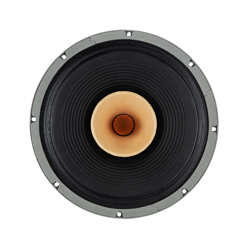
The fundamental purpose of any speaker enclosure is twofold. First, it must provide a stable, non-resonant housing for the speaker driver. On a basic level, the enclosure keeps all the components in one unit and holds the drivers in the correct position to work together effectively. Second, and more critically, it must solve a fundamental problem of physics known as the "acoustic short circuit." A speaker driver creates sound by moving a diaphragm back and forth. As it moves forward, it creates a positive pressure wave (sound); as it moves backward, it creates a negative pressure wave. The radiation from the rear side is in antiphase with the front side radiation. At low frequencies, where the sound waves are very long, these two opposing waves wrap around the driver and cancel each other out. The result is a dramatic attenuation of bass. The enclosure's primary job is to block this rear wave, separating it from the front wave and allowing low frequencies to propagate properly.
Why Sealed Enclosures?
Among the various types of enclosures—ported, bandpass, transmission line—the sealed design is celebrated for a distinct set of characteristics that make it highly desirable, particularly for audiophiles who prioritize accuracy and detail.
- Excellent Transient Response: This is the hallmark of a sealed enclosure. "Transient response" refers to a speaker's ability to start and stop moving precisely with the musical signal. Sealed boxes are known for delivering improved transient response, which translates to bass that is often described as "tight," "accurate," and "controlled". The air trapped inside the airtight box acts like a spring or a shock absorber, helping to damp the driver's movement and prevent it from overshooting or ringing after a note has ended. This makes them ideal for reproducing the sharp attack of a kick drum or the intricate texture of a bass guitar.
- Simple Design and Construction: Compared to ported or bandpass designs, which require precise calculation of port dimensions and tuning frequencies, the sealed enclosure is refreshingly straightforward. The difficulty of construction is very easy; you just have to make sure the box doesn’t leak air. The primary variable you need to calculate is the internal volume, making it a much more forgiving project for beginners.
- Forgiving of Small Errors: A slight miscalculation in volume for a ported or bandpass box can be disastrous to the final sound. In contrast, a sealed enclosure is less critical. If you aimed for a 25-liter box and ended up with 28 liters due to construction errors, it will still sound good. This forgiving nature reduces the pressure on the first-time builder.
However, this performance comes with a well-understood trade-off: lower efficiency. The air spring that provides such excellent control also resists the driver's movement, meaning it requires more amplifier power to produce the same sound pressure level (SPL) as a comparable ported design. Ported enclosures are generally more efficient and allow you to use a smaller amplifier than you would need with a sealed enclosure. A sealed box will sound tight and deep, but not as loud unless you are feeding it significant power.
This guide is built on a clear premise: by understanding a few key technical specifications, you can move beyond guesswork and methodically design a sealed speaker enclosure that is acoustically optimized for your chosen driver. We will walk through a step-by-step process, transforming a list of numbers—the Thiele/Small parameters—into a blueprint for a predictable, high-quality, and deeply satisfying audio experience.
Part 1: Decoding the Driver - Understanding Key Thiele/Small Parameters
Before a single piece of wood is cut, the journey of designing a high-performance speaker enclosure begins with understanding its most critical component: the driver. A speaker driver is not just a cone that moves; it is a complex electromechanical motor with a unique set of characteristics. These characteristics are quantified by a set of specifications known as Thiele/Small (T/S) parameters, which are the essential ingredients for our design recipe.
What are Thiele/Small (T/S) Parameters?
Thiele/Small parameters are a set of electromechanical measurements that define the low-frequency performance of a speaker driver. Developed in the early 1970s through seminal papers presented to the Audio Engineering Society (AES) by A.N. Thiele and Richard H. Small, these parameters revolutionized loudspeaker design. Prior to their work, there were no easy or standardized methods for obtaining this data. Their research provided a framework that allows designers to accurately predict how a driver will behave when placed inside a specific enclosure, moving the process from a trial-and-error art to a predictable science.
While there are dozens of T/S parameters, for designing a sealed enclosure, we only need to focus on a critical few. These parameters describe the driver's mass, suspension stiffness, and motor strength, which together determine its acoustic output.
The "Big Three" for Sealed Enclosures
To design a sealed enclosure, you must intimately understand three primary T/S parameters provided by the driver manufacturer. These form the foundation of all our calculations.
- Fs (Free Air Resonance): This is the natural frequency at which the driver's moving parts (the cone, voice coil, and suspension) vibrate when suspended in free air with no enclosure. Measured in Hertz (Hz), Fs is the point where the driver moves most efficiently with the least resistance. As a general rule, a lower Fs suggests the driver has better potential for deep bass reproduction. For example, a subwoofer with an Fs of 25 Hz will typically be able to play lower notes than one with an Fs of 40 Hz. It represents the practical low-frequency limit of the driver itself.
- Qts (Total Q): Qts, or Total Quality Factor, is a unitless measurement that describes the driver's combined damping characteristics at its resonant frequency (Fs). It is a composite value derived from the driver's mechanical damping (Qms) and electrical damping (Qes).
- Qms represents the mechanical control from the speaker's suspension system—the flexible surround and the spider—which act like shock absorbers.
- Qes represents the electrical control from the motor system—the voice coil and magnet. As the coil moves through the magnetic field, it generates a counter-electromotive force (back EMF) that opposes the motion, providing electrical damping.
- Vas (Equivalent Compliance Volume): This parameter can be tricky to grasp, but it's crucial. Vas represents a volume of air that has the same stiffness (compliance) as the driver's own mechanical suspension. It is measured in liters or cubic feet and describes the volume of air that, when compressed, exerts the same force as the driver's suspension (Cms). A driver with a very stiff suspension will have a low Vas, while a driver with a very loose, compliant suspension will have a high Vas. This parameter is essential because it helps determine the ideal enclosure size; typically, drivers with a lower Vas are better suited for smaller enclosures.
A Quick Check: The Efficiency Bandwidth Product (EBP)
Before committing to a sealed design, a quick calculation can confirm if your chosen driver is truly a good candidate. The Efficiency Bandwidth Product (EBP) provides a strong indication of the type of enclosure a driver is best suited for. The formula is simple:
EBP = Fs / QesOnce you calculate the EBP, you can apply a widely accepted rule of thumb:
- EBP around 50 or less: The driver is ideal for a sealed enclosure. Its motor is strong enough relative to its resonance to work well with the air spring of a closed box.
- EBP between 50 and 100: The driver is flexible and can work well in either a sealed or a ported enclosure. The final choice depends on the design goals (e.g., tight bass vs. maximum output).
- EBP above 90-100: The driver is strongly recommended for a ported (vented) enclosure. It is designed to be efficient and will likely perform poorly in a sealed box, often resulting in thin, weak bass.
By understanding these fundamental parameters—Fs, Qts, and Vas—and performing a quick EBP check, you have all the necessary information to move from theory to practice. You are now ready to use these ingredients to design the heart of your speaker system: the enclosure itself.
Part 2: The Blueprint - Calculating Your Enclosure Volume
With a firm grasp of the driver's key parameters, we can now transition to the most critical phase of the design process: determining the physical volume of the enclosure. This is where science meets intent. The size of the box is not arbitrary; it is precisely calculated to achieve a specific acoustic outcome. The central goal is to manipulate the driver's performance to match our desired sound character, a character defined by a single, crucial parameter: Qtc.
Step 1: Defining Your Goal - Choosing a Target Qtc
If Qts is the driver's inherent Q factor in free air, then Qtc is the total Q of the driver *after* it has been installed in a sealed enclosure. The 'c' stands for "closed box." When a driver is placed in an airtight box, the trapped air acts as an additional spring, stiffening the overall suspension. This pneumatic damping from the air inside the box contributes to the total damping of the system. As the box volume decreases, the "air spring" becomes stiffer, and the Qtc value increases. Therefore, by choosing a specific box volume, we are effectively choosing a target Qtc.
Qtc denotes the enclosure's ability to control the driver's response at resonance and is the single most important design decision you will make, as it directly dictates the bass performance, including frequency response, roll-off characteristics, and transient accuracy. The choice of Qtc is a balance between objective flatness and subjective preference.
The Spectrum of Sound: Visualizing Qtc
The relationship between Qtc and frequency response is best understood visually. The chart below illustrates how a sealed system's low-frequency output changes with different Qtc values. All curves eventually converge at higher frequencies, but their behavior in the critical bass region is dramatically different.
Here is a breakdown of what each Qtc value means for the sound you will hear:
- Qtc = 0.5 (Overdamped): This alignment provides the most accurate transient response possible—theoretically "perfect." However, it comes at the cost of efficiency and bass extension. The bass begins to roll off at a higher frequency, resulting in a sound that may be perceived as thin or lacking in weight. It is often used in high-end studio monitors where absolute accuracy is paramount.
- Qtc = 0.707 (Critically Damped / "Maximally Flat"): This is the gold standard and the most recommended target for beginners and audiophiles alike. It is the value most people try to reach for, as it gives good transients and a flat frequency response with the lowest possible cutoff frequency before any peaking occurs. It represents the ideal balance between accurate, tight bass and good low-frequency extension.
- Qtc = 0.8 - 1.0 (Slightly Underdamped): In this range, the system starts to exhibit a noticeable "bump" or peak in the bass response just before it rolls off. This can produce a "fun" or "warm" sound with more perceived bass impact, but it comes at the expense of some transient accuracy and can sound slightly less defined. This is a popular choice for car audio or for those who prefer a bit more low-end presence.
- Qtc > 1.2 (Highly Underdamped): This range should generally be avoided. The bass peak becomes very pronounced, leading to a boomy, uncontrolled, and "one-note" bass where a narrow range of frequencies dominates all others. This is only considered when enclosure size is an extreme constraint, as it sacrifices sound quality for compactness.
Step 2: The Magic Formula - Calculating Net Volume (Vc)
Once you have chosen your target Qtc, you can calculate the required net internal volume of your enclosure (Vc) using a cornerstone formula of sealed box design. This formula directly links the driver's parameters to your design goal.
Vc = Vas / [ (Qtc / Qts)² - 1 ]Let's break down the components:
Vc: The Net Internal Volume of the enclosure you are solving for (in the same units as Vas).Vas: The Equivalent Compliance Volume of your driver (from the spec sheet).Qtc: Your chosen target Q for the system (e.g., 0.707).Qts: The Total Q of your driver (from the spec sheet).
Practical Application: A Worked Example
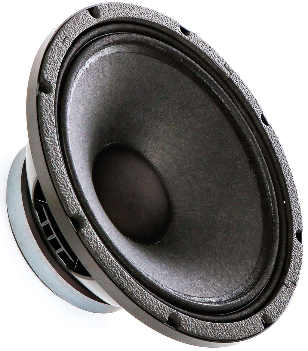
Let's design an enclosure for a hypothetical 6.5" mid-woofer with the following Thiele/Small parameters, which are similar to those found in some real-world drivers used in DIY projects :
- Vas: 49 liters
- Qts: 0.26
- Fs: 30 Hz
Our goal is a maximally flat response, so we will choose a target Qtc of 0.707.
Now, we plug the values into the formula:
Vc = 49 / [ (0.707 / 0.26)² - 1 ]
Vc = 49 / [ (2.719)² - 1 ]
Vc = 49 / [ 7.393 - 1 ]
Vc = 49 / 6.393
Vc ≈ 7.66 liters
The calculation shows that to achieve our target Qtc of 0.707 with this specific driver, we need a sealed enclosure with a net internal volume of approximately 7.66 liters. While understanding this formula is empowering, for convenience, many builders use online calculators or dedicated software. Programs like BassBox Pro or free tools like WinISD can perform these calculations instantly and provide detailed graphs, but they are all built upon this fundamental mathematical relationship.
Step 3: From Net to Gross - Accounting for Real-World Volume
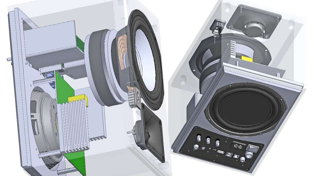
The calculated `Vc` (7.66 liters in our example) is the *net* internal air volume the driver requires to perform as intended. However, the physical box you build must be larger to account for the volume displaced by the components inside it. The volume occupied by the speaker driver(s), bracing materials, and any internal crossover or terminals needs to be added to the total volume calculated.
- Driver Displacement: The magnet structure and basket of the driver itself take up significant space. This volume must be added to `Vc`. Manufacturers sometimes provide this value, but if not, it can be estimated. Online tools like the Driver Displacement Calculator can provide a good estimate based on the driver's physical dimensions. For a typical 6.5" driver, this might be around 0.6 liters.
- Bracing Displacement: Internal braces are crucial for rigidity but also occupy volume. You must estimate the volume of your bracing (length x width x height for each piece) and add it to the total. For a small box, this might be 0.2 to 0.5 liters.
- Other Components: If the crossover network and speaker terminals are mounted inside the enclosure, their volume must also be accounted for.
The final calculation for the physical box you need to build is:
Gross Box Volume = Vc + Driver Displacement + Bracing Displacement + ...Using our example:
Gross Box Volume = 7.66 L + 0.6 L (driver) + 0.3 L (bracing) = 8.56 litersThis gross volume is the target you will use to determine the final external dimensions (Height x Width x Depth) of your speaker box, taking into account the thickness of the material you will use for construction.
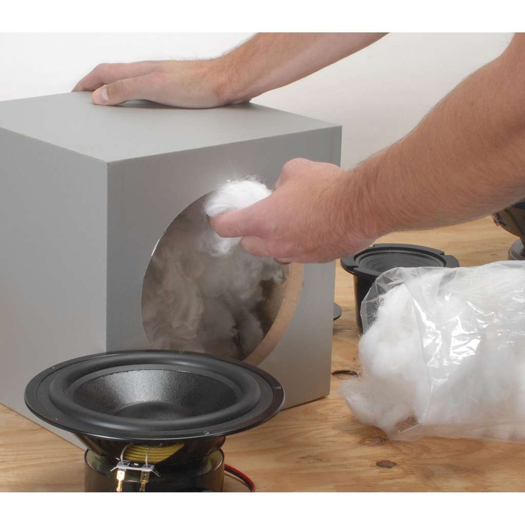
Part 3: The Finishing Touch - The Art and Science of Damping
Once the enclosure volume is calculated and the box is built, there is one final, crucial step to refine its performance: the addition of internal damping material. This is often referred to as "stuffing" or "filling" the enclosure. While it may seem like a simple act of adding fluffy material, damping is a nuanced process that serves multiple acoustic purposes, transforming a good enclosure into a great one by controlling unwanted resonances and subtly altering the box's acoustic properties.
Why Add Stuffing to a Box?
The addition of damping material like polyfill, fiberglass, or wool inside a sealed enclosure has two primary and significant effects on the sound.
1. Taming Internal Reflections and Standing Waves
The primary and most intuitive goal of damping is to absorb sound energy inside the box. When the driver moves, it radiates sound not only forward into the room but also backward into the enclosure. These back waves bounce off the internal panels. Without damping, these reflections can travel back towards the speaker cone and pass through it, coloring the sound that reaches the listener. This can create audible resonance, a "boxy" or "hollow" coloration, and degrade the overall clarity, especially in the midrange frequencies. Damping material placed on the walls and within the volume of the enclosure effectively absorbs this unwanted energy, particularly at mid and high frequencies, ensuring that the sound you hear is predominantly the direct radiation from the front of the driver.
2. The "Magic" Effect: Increasing Apparent Volume
The second effect is less intuitive but profoundly important. Adding the correct amount of damping material can make the enclosure "act" acoustically larger than its physical dimensions. Stuffing can increase the effective frequency range downward because the internal sound wave is slowed, making the box seem larger to the driver. This phenomenon is due to a change in the thermodynamic process inside the box.
- An empty box operates under **adiabatic** conditions (no heat transfer). When the air is compressed quickly, its temperature rises, increasing its pressure and stiffness.
- A properly stuffed box operates closer to **isothermal** conditions (constant temperature). The vast surface area of the fibers in the damping material absorbs and dissipates the heat generated by air compression. This heat transfer lowers the pressure change for a given volume change.
This reduction in pressure makes the air "spring" less stiff, which is acoustically equivalent to being in a larger box. This effect can increase the apparent or acoustical volume (Vab) by a factor (α) of up to 1.4, though a more conservative estimate is typically 15-25%. This "free" extra volume can lower the system's final resonant frequency (fc) and Qtc, resulting in deeper bass extension and a smoother frequency response.
Choosing Your Damping Material
Several materials are commonly used for damping, each with its own pros and cons.
- Polyfill (Polyester Fiberfill): This is the most common choice for DIY builders. It is inexpensive, widely available (as pillow or quilt stuffing), safe, and easy to handle. It is very effective and provides a great balance of performance and convenience.
- Fiberglass Insulation: Acoustic tests have repeatedly shown that fiberglass is one of the most effective materials for both absorption and achieving the isothermal effect. However, it sheds tiny, irritating fibers that can be harmful if inhaled. If using fiberglass, it is crucial to wear gloves, a mask, and protective clothing during handling. It should also be covered with a thin, acoustically transparent cloth inside the enclosure to prevent fibers from escaping.
- Natural Wools and Cottons: Materials like long-fiber wool or dense cotton batting are also excellent acoustic dampers. Some high-end manufacturers use materials like sheep wool. They can be very effective but are often significantly more expensive than polyfill or fiberglass.
How Much is Too Much?
Finding the right amount of damping is a balancing act. There are risks associated with using both too little and too much material.
- The Risk of Under-damping: Using too little material will fail to adequately control internal reflections, which can lead to a resonant, "hollow," or "boxy" sound signature. The benefits of increased apparent volume will also be minimal.
- The Risk of Over-damping: Adding too much damping material can make the speaker sound dull and lifeless. If the material is crammed in too tightly, it can begin to restrict airflow and actually reduce the effective internal volume. This can lead to a reduced bass response and a "muddy" sound due to insufficient energy transfer and an overly controlled driver.
Best Practice and Guidelines
A good starting point is to aim for a specific density. A widely cited guideline is to use approximately 1.0 to 1.5 pounds of fiberfill per cubic foot of enclosure volume (or about 16-24 grams per liter). The material should be gently fluffed up and distributed evenly throughout the enclosure, leaving a small, clear space directly behind the driver's magnet to allow it to "breathe."
Ultimately, the final amount should be determined by listening. Start with the calculated amount, then add or subtract small portions of stuffing to fine-tune the response. Listen for the point where the bass is tight, defined, and articulate, without sounding overly dry or boomy. This final tuning by ear is where the "art" of speaker building complements the "science" of the design.
Part 4: Bringing It to Life - Construction Best Practices
With the design finalized, the calculations complete, and an understanding of damping in hand, it's time to turn the blueprint into a physical reality. The quality of construction is just as important as the accuracy of the design. A poorly built box can undermine even the most perfect calculations, introducing rattles, resonances, and leaks that degrade sound quality. Adhering to a few key best practices will ensure your enclosure is as solid and acoustically inert as possible.
Material Matters
The choice of material for your enclosure has a significant impact on its acoustic performance. The ideal material is dense, stiff, and well-damped, meaning it resists vibration and does not have its own strong resonant character.
- MDF (Medium-Density Fiberboard): This is the undisputed king for DIY speaker building. MDF is excellent for boosting bass response because it is dense, acoustically inert, and affordable. Its uniform consistency, with no voids or grain, makes it easy to machine and finish.
- Plywood (Baltic Birch): High-quality, void-free plywood like Baltic Birch is another excellent choice. It is generally stronger and lighter than MDF for the same thickness, but it is also more expensive and its layered nature can make finishing more challenging.
- Thickness: For most bookshelf speakers and small subwoofers, a thickness of 3/4" (or 18mm) is the standard recommendation. For larger enclosures or high-power subwoofers that will generate immense internal pressure, increasing the thickness to 1" (25mm) or even using double-thick baffles (the front panel where the driver is mounted) is advisable.
Two Golden Rules for Sealed Enclosures
If you remember nothing else about construction, let it be these two principles. They are the foundation of a high-performance sealed enclosure.
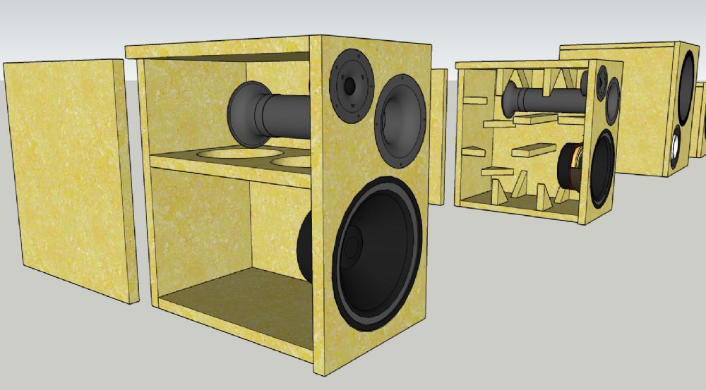
1. Rigidity is King
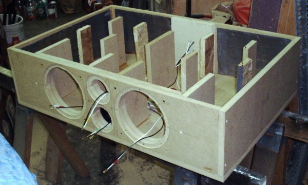
The enclosure should be an immovable, silent partner to the driver. Any vibration in the cabinet walls is, by definition, a form of distortion. A vibrating panel becomes a secondary, uncontrolled sound source that muddies the output of the driver. Internal bracing is the most effective way to increase the rigidity of an enclosure without dramatically increasing its weight or thickness. A well-braced 3/4" MDF box will almost always outperform a thicker, unbraced box. Braces should connect opposite panels (e.g., side-to-side, top-to-bottom) to counteract the flexing forces. "Window" braces, which are panels with large cutouts, are particularly effective as they add stiffness in multiple directions while minimally impacting airflow and internal volume.
2. It MUST Be Airtight
This rule is non-negotiable for a sealed enclosure. The entire acoustic principle of the design relies on the trapped volume of air acting as a perfect spring. Any leak, no matter how small, will compromise the design. A leak turns your carefully calculated acoustic suspension system into a poorly designed, uncontrolled ported box, often resulting in audible whistling or "chuffing" noises and a complete loss of the tight, controlled bass you worked to achieve. To ensure an airtight seal:
- Use a high-quality wood glue on all joints during assembly.
- After the glue has dried, apply a bead of silicone sealant or caulk to all internal seams and corners.
- Ensure speaker terminals are sealed. Use terminals with a gasket or apply a sealant around them.
- Mount the driver using a foam or rubber gasket between its frame and the baffle to create a perfect seal.
Final Assembly
The construction process typically follows a logical sequence. First, cut all panels to their precise dimensions—remember the old adage, "measure twice, cut once."; Assemble the box panel by panel, using wood glue and clamps to ensure tight joints. Screws can be used for additional strength but are not a substitute for good glue joints. Once the main box is assembled and the glue is dry, apply the internal sealant. Install the damping material and the speaker wire terminals. Finally, solder the wires to the driver, place the driver gasket on the baffle, and screw the driver securely into place, being careful not to overtighten and strip the holes or damage the driver's frame.
Conclusion: Your First Step into High-Fidelity Sound
The journey from a set of raw specifications to a finished, high-performing loudspeaker is one of the most gratifying experiences in the world of audio. We have navigated the entire process, demystifying the science that governs the heart of any great speaker system. By following this guide, you have learned to translate the abstract language of Thiele/Small parameters into a tangible, predictable, and exceptional sonic result.
Let's recap the core stages of this journey:
- Understand Your Driver: We started by decoding the essential T/S parameters—Fs, Qts, and Vas—which define the driver's fundamental acoustic DNA.
- Choose Your Sound Goal: We established that the target Qtc is the most critical design choice, allowing you to dictate the final character of the bass, from "critically damped" accuracy (0.707) to "fun" warmth (0.8-1.0).
- Calculate the Volume: Using a fundamental formula, we transformed these parameters and goals into a precise net internal volume (Vc), the acoustic space your driver needs to thrive.
- Account for Reality: We adjusted the net volume to a gross volume by accounting for the physical displacement of the driver, bracing, and other components.
- Refine with Damping: We explored the art of applying internal damping material to control reflections and increase the apparent acoustic volume, fine-tuning the sound to perfection.
- Build with Precision: Finally, we emphasized the two golden rules of construction for a sealed enclosure: make it rigid and make it airtight.
The sealed enclosure, in its elegant simplicity, is the perfect teacher. It is forgiving of minor errors yet rewards precision and care with a sound quality that is pure, accurate, and deeply musical. It provides a natural, well-balanced bass sound that is suitable for critical listening and audiophile-grade systems. While the process is rooted in science and mathematics, the final result is an emotional one—the pride and joy of listening to music through a system you built with your own hands.
Now, the blueprint is yours. Find a driver that speaks to you, gather your tools, and begin the process. Embrace the challenge, enjoy the learning, and prepare to experience your favorite music in a way you never thought possible—through a speaker that is uniquely, wonderfully, and perfectly yours.