
The Enduring Legacy of the 1969 JLH Class A Amplifier
Published by IWISTAO
Introduction: A Landmark in Hi-Fi History
In the annals of high-fidelity audio, few designs have achieved the legendary status and enduring popularity of the 1969 Class A amplifier by John Linsley-Hood. First published in the April 1969 issue of Wireless World, this elegant and deceptively simple circuit emerged during a pivotal era of audio technology—the transition from vacuum tubes to solid-state transistors [1, 2]. While transistor amplifiers offered advantages in size, cost, and power, the prevalent Class B and quasi-complementary designs of the time were often plagued by audible imperfections, most notably crossover distortion [3].
Audiophiles of the day held tube amplifiers, particularly designs like D.T.N. Williamson's landmark 1947 amplifier, as the benchmark for sonic purity [4, 5]. The Williamson amplifier set a high standard, aiming for less than 0.1% total harmonic distortion (THD) at full power, a feat achieved through a complex four-stage, push-pull triode design with a massive, high-quality output transformer [3, 6]. Linsley-Hood's objective was audacious: to create a solid-state amplifier that could meet or exceed this standard of performance, but with a dramatically simpler, more accessible, and transformerless design [1]. The result was a masterpiece of minimalist engineering that continues to be built, modified, and cherished by DIY enthusiasts and audiophiles over half a century later.
The Design Philosophy: Simplicity and Purity
Why Class A?
Linsley-Hood's fundamental design choice was to operate the output stage in Class A. In a Class A amplifier, the amplifying devices (transistors, in this case) are always conducting current, regardless of the input signal. This means they operate over the full 360° of the signal waveform, ensuring the highest possible linearity [7, 8]. This approach directly addressed the primary sonic flaw of contemporary Class B designs. In Class B, two transistors work in a push-pull arrangement, with each handling one half (180°) of the waveform. The transition between the two transistors can be imperfect, creating crossover distortion, which is particularly noticeable at low volumes [3].

By choosing Class A, Linsley-Hood deliberately prioritized sonic purity over efficiency. This configuration inherently avoids crossover distortion, asymmetry issues found in quasi-complementary circuits, and signal-dependent variations in power supply current demand [1]. However, this choice comes with significant trade-offs. Because the transistors are always on and biased to handle the maximum signal swing, they dissipate a large amount of power as heat, even with no signal present. This results in very low power-conversion efficiency—theoretically a maximum of 25% with a simple resistive load, and often only 10-20% in practice [7, 8]. Consequently, the JLH 1969 requires substantial heat sinks to prevent the output transistors from overheating, a characteristic that has become a visual signature of the design [1].
An Elegant, Minimalist Circuit
The genius of the JLH 1969 lies in its "less is more" philosophy. The entire amplifier consists of only four transistors arranged in three stages, a stark contrast to the increasingly complex Class B designs of the era [2, 3]. Each component has a clear and vital role, creating a circuit that is both simple to understand and remarkably effective.

The circuit can be broken down as follows [2]:
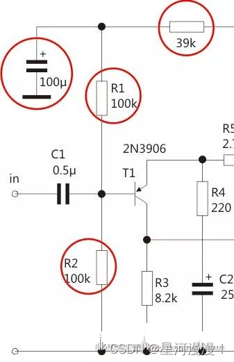
- Input Stage (Tr1): A single PNP transistor (originally a 2N3906) acts as the input voltage amplifier. It receives the audio signal and also serves as the injection point for the negative feedback loop, which is crucial for lowering distortion and stabilizing the circuit.
- Driver/Phase Splitter Stage (Tr2): This NPN transistor (originally a 2N1613 or similar) is arguably the most clever part of the design. It serves two functions simultaneously: it provides further voltage amplification (driving the output stage) and acts as a phase splitter. It delivers an in-phase signal to the upper output transistor (Tr3) and an out-of-phase signal to the lower output transistor (Tr4), enabling push-pull operation.
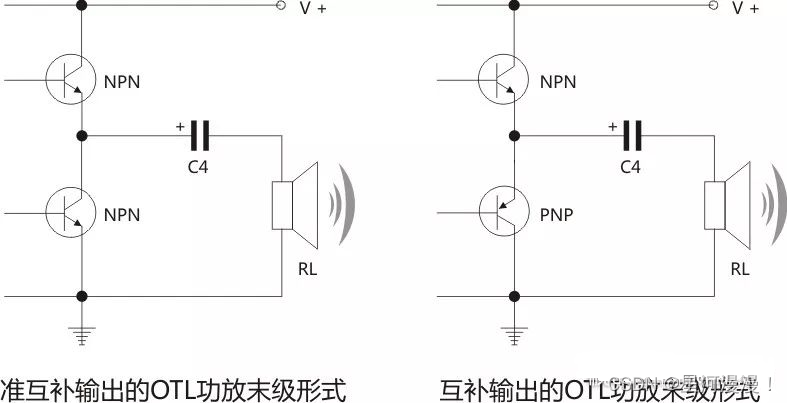
- Output Stage (Tr3 & Tr4): This is a single-ended push-pull (SEPP) output stage using two identical NPN power transistors (originally MJ480/481, with 2N3055 being a common modern substitute). Tr3 acts as an emitter follower, while Tr4 acts as a constant current source whose current is modulated by the signal from Tr2. This configuration allows the load to be driven effectively in both directions of the waveform [1, 2].
Deep Dive into the Circuit's Key Features
The Unique Output Stage
Unlike conventional push-pull amplifiers that use complementary pairs of NPN and PNP transistors, the JLH 1969 uses two identical NPN power transistors for the output [2]. This was a practical choice, as high-quality silicon NPN power transistors were more readily available and offered better performance and lower cost than their PNP counterparts in the 1960s [1].

To make this work, the driver stage (Tr2) must provide two signals of opposite phase. Linsley-Hood achieved this elegantly by taking one output from Tr2's collector and the other from its emitter [2]. The upper transistor (Tr3) functions as a collector load for the lower transistor (Tr4). This arrangement not only simplifies the parts list but also contributes to the amplifier's low distortion. As Linsley-Hood noted, the non-linearities of the two output transistors tend to cancel each other out, as one is turning full on while the other approaches cutoff [1].
Gain and Negative Feedback
A cornerstone of high-fidelity amplifier design is the use of negative feedback to reduce distortion, lower output impedance, and stabilize performance. The JLH 1969 employs a significant amount of feedback. The open-loop gain of the circuit is approximately 600 (or 55 dB) [1, 2]. The output signal is taken from the junction of the two output emitters and fed back to the emitter of the input transistor (Tr1) via resistor R5.
The closed-loop gain is determined by the ratio of the feedback resistors, specifically (R4 + R5) / R4. With the original component values, this results in a gain of about 13 (or 22 dB) [1, 2]. The difference between the open-loop and closed-loop gain gives a feedback factor of approximately 33-34 dB, a substantial amount that is responsible for the amplifier's impressively low distortion and an output impedance of about 160 milliohms [1].
The Bootstrap and Soft-Start Mechanisms
The circuit includes several other clever design elements. Capacitor C3, connected from the output to the junction of R1 and R2, forms a bootstrap circuit. This technique feeds a portion of the output signal back to the bias network of the driver stage. Its purpose is to make the driver transistor's collector load appear much larger than it actually is, allowing for a larger voltage swing and improving linearity and efficiency [2]. While effective, this is a feature some modern builders replace with a constant current source (CCS) for theoretically better performance [2, 10].

Another subtle but important feature is the biasing network for the input transistor Tr1. The inclusion of a 39k resistor and a 100µF capacitor creates a slow-charging circuit at power-on. This causes the DC voltage at the output to rise gradually to its target of half the supply voltage over several seconds. This "soft-start" minimizes the turn-on "thump" that could otherwise damage the connected loudspeaker [2].

Performance and Sound Characteristics
Distortion and Power Output
Linsley-Hood's design goal was to achieve a distortion level of less than 0.05% at full power, a very ambitious target for its time [3]. The published measurements show that the amplifier comfortably met this goal. The total harmonic distortion (THD) at 9 watts into a 15-ohm load was measured at just 0.06% with matched output transistors [1]. A key characteristic of this Class A circuit is that distortion decreases linearly as the output power is reduced. This is in contrast to Class B amplifiers, where crossover artifacts can cause distortion to rise at lower levels [1]. The residual distortion is predominantly benign second-order harmonic, which many listeners find to be musically pleasant and is often described as adding "warmth" and "richness" to the sound, reminiscent of tube amplifiers [1, 12].
The original design was specified for 10 watts of output power. The required supply voltage and quiescent current depend on the speaker's load impedance. For example, driving a 15Ω load to 10W requires a 36V supply and 0.9A of quiescent current. For an 8Ω load, it requires a 27V supply and 1.2A, and for a 3Ω load, a 17V supply and 2.0A [1]. This highlights the critical relationship between power supply, load, and thermal management in a Class A design. While 10 watts may seem low by modern standards, it is more than sufficient for high-efficiency speakers or for bi-amping systems where it might drive tweeters [3].
The Subjective "JLH Sound"
Beyond the specifications, the JLH 1969 is renowned for its subjective sound quality. It is often described as having a smooth, warm, and detailed character, frequently compared to that of a high-quality single-ended triode (SET) tube amplifier [12]. This is attributed to its simple signal path, lack of crossover distortion, and the nature of its harmonic distortion profile. The sound is often perceived as being very musical and non-fatiguing, making it a favorite for long listening sessions. Its ability to render vocals and acoustic instruments with a natural, lifelike texture is particularly praised by its proponents.

Building and Modifying the JLH 1969 Today
The enduring appeal of the JLH 1969 is fueled by the vibrant DIY audio community. Countless kits, PCBs, and fully assembled versions are available from vendors worldwide . For many, building a 1969 amplifier is a rite of passage, offering a rewarding project that results in a genuinely high-performance amplifier [15].
Over the decades, numerous modifications and improvements have been proposed. Common mods include:
- Upgrading Components: Using modern, high-quality transistors, metal-film resistors, and audiophile-grade capacitors (especially for the input and output coupling capacitors) can yield significant sonic improvements.
- Constant Current Source (CCS): Replacing the bootstrap circuit (C3 and associated resistors) with a dedicated CCS can improve linearity and power supply rejection [2].
- DC-Coupled Output (OCL): Eliminating the large output coupling capacitor (C4) to create a direct-coupled (OCL) design. This requires adding a DC servo circuit to protect the speakers from DC offset but can improve bass response and transparency.
- MOSFET Output Stage: Substituting the bipolar junction transistors (BJTs) in the output stage with MOSFETs. This creates a "1969M" variant, which can offer a different sonic signature and potentially operate in Class AB for higher efficiency [10].
- Power Supply Enhancements: Using regulated power supplies or capacitor multipliers (electronic filters) can reduce noise and ripple, further cleaning up the sound [1].
Conclusion
The John Linsley-Hood 1969 Class A amplifier is more than just a vintage circuit; it is a testament to the power of elegant, thoughtful design. By prioritizing sonic purity and embracing simplicity, Linsley-Hood created an amplifier that not only challenged the performance of complex tube and solid-state designs of its day but also captured a musical quality that continues to resonate with listeners. Its legacy lives on not just in the yellowed pages of a 1969 magazine, but in the countless workshops and listening rooms around the world where enthusiasts continue to build, tweak, and enjoy its uniquely beautiful sound. It stands as a timeless reminder that in the pursuit of high fidelity, sometimes the simplest path is the most rewarding.
References
- [1] Linsley-Hood, J. L. (1969, April). "Simple Class A Amplifier." Wireless World. Available at: https://sound-au.com/tcaas/jlh1969.pdf
- [2] "Hood 1969 Class A 10W Power Amplifier Circuit Analysis)." (2024, May 27). CSDN. Available at: https://blog.csdn.net/qq_35240747/article/details/136416355
- [3] Linsley-Hood, J. L. (1969). "Simple Class A Amplifier" (annotated version). kaipanji.com.cn. Available at: http://kaipanji.com.cn/thread-80026-1-1.html
- [4] Dalmura, P. R. S. (2020, October 15). "The Williamson Amplifier: A brief history of the worlds first, true high fidelity amplifier." Available at: https://dalmura.com.au/static/The%20Williamson%20Amplifier%20History.pdf
- [5] Williamson, D. T. N. (1947). "Design for a High-Quality Amplifier." Wireless World.
- [6] "The Williamson Amplifier." (2012, January 5). r-type.org. Available at: https://www.r-type.org/pdfs/dtnw-amp.pdf
- [7] "High-Efficiency Power Amplifiers." (2019, February 19). Universitat Politècnica de Catalunya. Available at: https://upcommons.upc.edu/bitstreams/0922f39d-9fdb-4504-855d-2ba0bb04619d/download
- [8] "Class A amplifier." (2025, August 17). Analog Circuit Design. Available at: https://analogcircuitdesign.com/class-a-amplifier/
- [9] Image source from CSDN blog post. Available at: https://i-blog.csdnimg.cn/blog_migrate/04e0e554ccfb18de636a62302fc45dc2.png
- [10] "1969M Small Class A Amplifier Circuit Diagram and Analysis)." (2026, January 2). eeworld.com.cn. Available at: https://www.eeworld.com.cn/RDesigns_detail/77251
- [11] Image source from CSDN blog post. Available at: https://i-blog.csdnimg.cn/blog_migrate/c1f8381e9be01517f06d105699fb2b74.png
- [12] "BRZHIFI Power Amplifier Hood 1969 Class a Hifi Audio Close to Tube Amplifier." Alibaba.com. Available at: https://www.alibaba.com/product-detail/BRZHIFI-Power-Amplifier-Hood-1969-Class_1601214135434.htm
- [13] "DIY 1969 Small Class A Amplifier)." Quark Document. Available at: https://doc.quark.cn/preview/tongyongshenghuo-qita-qita/0A038AE06FFE756F5C50288FE841C163
No comments:
Post a Comment