Thursday, August 7, 2025

Building Audio Amplifiers with Germanium Transistors: A Journey into Vintage Electronics

Building Audio Amplifiers with Germanium Transistors: A Journey into Vintage Electronics

Published by IWISTAO

When most electronics enthusiasts think about building amplifiers today, silicon transistors and integrated circuits dominate the conversation. However, there's something uniquely satisfying about working with germanium transistors – the workhorses of early semiconductor technology that helped launch the transistor revolution in the 1950s and 1960s. In this comprehensive guide, we'll explore how to design and build an audio amplifier using these fascinating vintage components.

Understanding Germanium Transistors

What Makes Germanium Special?

Germanium transistors were the first commercially viable bipolar junction transistors (BJTs), preceding their silicon counterparts by several years. These devices exhibit several distinctive characteristics that set them apart from modern silicon transistors:

Key Characteristics:

  • Lower forward voltage drop: Germanium diodes typically have a forward voltage of about 0.2-0.3V compared to silicon's 0.7V
  • Higher leakage current: Germanium transistors exhibit significantly higher collector-base leakage current (ICBO)
  • Temperature sensitivity: More susceptible to thermal runaway than silicon devices
  • Lower maximum operating temperature: Typically limited to around 85°C compared to silicon's 150°C+
  • Unique sonic character: Many audiophiles claim germanium devices impart a "warmer" sound

Common Germanium Transistor Types

For audio applications, several germanium transistor types remain popular:

  • 2N404/2N404A: PNP general-purpose transistors, excellent for audio
  • OC71/OC72: European PNP transistors, widely used in vintage designs
  • 2N1307: PNP medium-power transistor suitable for output stages
  • AC128: PNP transistor popular in European audio circuits

Historical Context and Modern Relevance

The Golden Age of Germanium

From 1947 to the mid-1960s, germanium ruled the semiconductor world. Bell Labs' first transistor was made from germanium, and virtually all early transistor radios, amplifiers, and electronic devices relied on these components. Companies like Philips, Mullard, and RCA produced millions of germanium transistors that powered everything from hearing aids to early computers.

Why Germanium Still Matters Today

Despite being largely superseded by silicon technology, germanium transistors maintain relevance for several reasons:

  1. Historical reproduction: Restoring vintage equipment requires period-correct components
  2. Unique audio characteristics: Many guitarists and audiophiles prefer the sound of germanium-based circuits
  3. Educational value: Understanding germanium devices provides insight into semiconductor physics and early circuit design
  4. Specialty applications: Some modern designs specifically exploit germanium's unique properties

Basic Amplifier Design Principles

Single-Stage Common Emitter Amplifier

The foundation of most germanium amplifier designs is the common emitter configuration, which provides both voltage and current gain. Let's examine the basic topology:

VCC (+9V)
 |
 R1 (10kΩ)
 |
 +---- OUTPUT
 |
 C   
B|---E  Q1 (2N404A)
 |
 R2 (1kΩ)
 |
 GND

Biasing Considerations for Germanium

Proper biasing is crucial for germanium transistors due to their high leakage current and temperature sensitivity. The collector-base leakage current (ICBO) can be 10-100 times higher than equivalent silicon devices, significantly affecting bias stability.

Critical biasing factors:

  • Use voltage divider biasing with low-impedance bias networks
  • Account for ICBO in bias calculations
  • Consider temperature compensation techniques
  • Implement DC coupling carefully due to voltage offset variations

Step-by-Step Amplifier Construction

Project: Single-Stage Audio Amplifier

Let's build a practical single-stage audio amplifier using a 2N404A germanium PNP transistor.

Circuit Design

Our amplifier will feature:

  • Input impedance: ~2kΩ
  • Voltage gain: ~20dB
  • Output impedance: ~500Ω
  • Frequency response: 50Hz - 15kHz

Schematic Analysis

INPUT ----C1----+
               |
               R1
               |
VCC-----------R2----+----C3----OUTPUT
 |                  |
 |           Q1(2N404A)
 |               |
 +----R3---------+
 |               |
 C2              R4
 |               |
GND-----------GND

Component Values:

  • C1: 10µF (input coupling)
  • C2: 100µF (power supply decoupling)
  • C3: 22µF (output coupling)
  • R1: 47kΩ (base bias)
  • R2: 10kΩ (collector load)
  • R3: 22kΩ (bias stability)
  • R4: 2.2kΩ (emitter resistor)
  • Q1: 2N404A (germanium PNP)

Construction Steps

Step 1: Prepare the Circuit Board

Start with a small piece of perfboard or stripboard. The compact layout is important for minimizing noise and parasitic capacitance.

Step 2: Install the Transistor

Mount the 2N404A transistor first, paying careful attention to pinout. For TO-1 metal can packages:

  • Case connects to collector
  • The tab indicates emitter
  • Base is the remaining pin

Step 3: Add Resistors

Install resistors in order of increasing value to avoid confusion. Use 1% metal film resistors for best performance and stability.

Step 4: Install Capacitors

Use high-quality capacitors:

  • Tantalum or aluminum electrolytic for C1 and C3
  • Low-ESR electrolytic for C2

Step 5: Wiring and Connections

Keep wire lengths short to minimize noise pickup. Use shielded cable for input connections if needed.

Component Selection and Considerations

Choosing Germanium Transistors

When selecting germanium transistors for audio applications, consider these factors:

Gain (hFE): Look for devices with hFE between 50-150. Higher gain transistors may be more prone to oscillation.

Leakage Current: Measure ICBO at room temperature. Values above 50µA may cause bias stability issues.

Matching: For differential pairs or push-pull configurations, match transistors for hFE and ICBO within 10%.

Supporting Components

Resistors: Use 1% tolerance metal film resistors for critical bias components. Carbon composition resistors can add vintage character but may introduce noise.

Capacitors:

  • Input/output coupling: Use film capacitors (polyester or polypropylene) for best audio performance
  • Power supply decoupling: Low-ESR aluminum electrolytic capacitors

Power Supply: Clean, well-regulated DC supply. Germanium circuits are more sensitive to supply noise than silicon equivalents.

Circuit Analysis and Calculations

DC Analysis

For our example circuit, let's calculate the operating point:

Assumptions:

  • VCC = 9V
  • hFE = 80 (typical for 2N404A)
  • ICBO = 10µA
  • VBE = 0.2V (germanium)

Base voltage calculation:
VB = VCC × R3/(R1 + R3) = 9V × 22kΩ/(47kΩ + 22kΩ) = 2.87V

Emitter voltage:
VE = VB - VBE = 2.87V - 0.2V = 2.67V

Emitter current:
IE = VE/R4 = 2.67V/2.2kΩ = 1.21mA

Collector current:
IC ≈ IE = 1.21mA

Collector voltage:
VC = VCC - (IC × R2) = 9V - (1.21mA × 10kΩ) = -3.1V

AC Analysis

Input impedance:
Zin = R1 || R3 || (hFE × R4) = 47kΩ || 22kΩ || (80 × 2.2kΩ) ≈ 2.1kΩ

Voltage gain:
Av = -R2/R4 = -10kΩ/2.2kΩ ≈ -4.5 (13dB)

Output impedance:
Zout ≈ R2 = 10kΩ

Construction Tips and Best Practices

Layout Considerations

  1. Ground plane: Use a solid ground plane or star grounding to minimize noise
  2. Component placement: Keep the transistor away from heat sources
  3. Lead dress: Route input and output leads away from each other to prevent feedback
  4. Shielding: Consider metal enclosure for RF immunity

Handling Germanium Transistors

Germanium transistors require special care:

  • Static sensitivity: While less ESD-sensitive than modern devices, use basic anti-static precautions
  • Thermal shock: Allow components to reach room temperature before handling
  • Lead forming: Make bends gradually to avoid crystal damage
  • Storage: Keep in anti-static foam or tubes

Soldering Techniques

  • Use low-temperature solder (60/40 rosin core)
  • Keep iron temperature below 300°C
  • Work quickly to minimize heat exposure
  • Use heat sinks on transistor leads when necessary

Testing and Troubleshooting

Initial Checkout

Before applying power, perform these checks:

  1. Visual inspection: Verify all connections and component orientations
  2. Continuity test: Check for short circuits, especially power supply rails
  3. Resistance measurements: Verify bias resistor values

Power-On Testing

With a current-limited power supply:

  1. Quiescent current: Should be 1-2mA for our example circuit
  2. DC voltages: Measure and compare to calculated values
  3. Signal injection: Apply small AC signal and verify amplification

Common Problems and Solutions

No output signal:

  • Check transistor pinout
  • Verify coupling capacitors aren't reversed
  • Measure DC bias voltages

Distorted output:

  • Bias point may be incorrect
  • Check for thermal runaway (rising collector current over time)
  • Verify input signal level isn't too high

Oscillation:

  • Add small capacitor (100pF) across collector-base
  • Check lead dress and layout
  • Reduce high-frequency gain if necessary

Thermal instability:

  • Improve heat sinking
  • Consider temperature compensation
  • Check for excessive ambient temperature

Performance Characteristics and Limitations

Frequency Response

Germanium transistors typically have lower transition frequency (fT) compared to modern silicon devices. Expect:

  • Useful audio bandwidth: DC to 20kHz
  • 3dB rolloff: Usually above audio range for single-stage designs
  • Phase response: Generally good for audio applications

Noise Characteristics

Germanium transistors exhibit higher noise than modern silicon devices:

  • Thermal noise: Similar to silicon at room temperature
  • Shot noise: Higher due to increased leakage current
  • 1/f noise: Can be significant at low frequencies

Temperature Stability

This remains the primary limitation:

  • Thermal runaway: More prone than silicon circuits
  • Bias drift: Significant over temperature range
  • Maximum operating temperature: Limited to ~85°C

Audio Performance

Despite technical limitations, many listeners prefer germanium amplifiers for:

  • Harmonic character: Predominantly even-order harmonics
  • Compression characteristics: Gradual clipping behavior
  • Frequency response: Often has pleasing high-frequency rolloff

Advanced Techniques

Temperature Compensation

For improved stability, consider these techniques:

Thermistor compensation:
Replace part of the emitter resistance with a negative temperature coefficient thermistor.

Diode compensation:
Use germanium diodes in the bias network to track VBE temperature variations.

Thermal coupling:
Mount compensation components in thermal contact with the transistor.

Push-Pull Output Stages

For higher power output:

VCC
 |
 R1
 |
INPUT----+----Q1 (PNP)----+----OUTPUT
         |                |
         +----Q2 (NPN)----+
         |                |
         R2               |
         |                |
        GND--------------GND

Use matched complementary pairs (2N404A PNP with 2N1306 NPN).

Feedback Techniques

Implement negative feedback for:

  • Improved linearity
  • Reduced distortion
  • Better frequency response
  • Enhanced stability

Maintenance and Long-term Reliability

Expected Lifespan

Well-designed germanium circuits can operate reliably for decades:

  • Avoid temperature extremes
  • Maintain clean, stable power supplies
  • Protect from humidity and contamination

Replacement Considerations

When germanium transistors fail:

  • Source quality NOS (New Old Stock) devices
  • Consider modern germanium reproductions
  • Match replacement devices carefully
  • Some silicon substitutes available but change circuit character

Conclusion

Building amplifiers with germanium transistors offers a unique glimpse into electronics history while producing circuits with distinctive sonic characteristics. While these devices present challenges – thermal instability, higher noise, and limited availability – they reward careful design and construction with a musical quality that many find appealing.

The key to successful germanium amplifier design lies in understanding and accommodating these transistors' unique properties rather than fighting them. Proper biasing, thermal management, and component selection are crucial for reliable operation.

Whether you're restoring vintage equipment, exploring audio circuit design, or simply seeking that elusive "vintage tone," germanium transistors provide an educational and rewarding platform for experimentation. The skills learned working with these temperamental devices – careful bias design, thermal analysis, and attention to construction detail – translate directly to more advanced analog circuit design.

As we've seen, germanium transistors may be vintage technology, but they still have much to teach us about the fundamentals of semiconductor devices and analog circuit design. In an age of digital processing and integrated circuits, there's something refreshingly hands-on about building an amplifier one discrete component at a time, especially when those components helped launch the semiconductor revolution nearly 75 years ago.

So fire up your soldering iron, dust off that vintage multimeter, and dive into the fascinating world of germanium electronics. Your ears – and your understanding of analog circuit design – will thank you.

Tuesday, August 5, 2025

The FU50 Amplifier: Unpacking the "Little 300B" Legend

The FU50 Amplifier: Unpacking the "Little 300B" Legend

The FU50 Amplifier: Unpacking the "Little 300B" Legend

In an era dominated by digital precision and solid-state efficiency, the warm, glowing heart of the vacuum tube amplifier continues to captivate audiophiles. It represents a connection to the golden age of audio, a time when sound was sculpted by hand-wired circuits and glowing glass. Among the pantheon of audio tubes, some are legends, like the Western Electric 300B. Others are unsung heroes. The FU50 falls into the latter category—a rugged, military-grade pentode that has found a second life as the core of surprisingly musical and affordable Hi-Fi amplifiers, earning it the intriguing nickname: the ";little 300B."

From Battlefield to Listening Room: The Unlikely History of the FU50

The story of the FU50 is a fascinating journey through 20th-century geopolitics and technology transfer. Its lineage begins not in an audio lab, but in wartime Germany with the Telefunken LS-50 power pentode. This robust tube was designed for radio frequency (RF) applications in military equipment. After World War II, its design was replicated in the Soviet Union as the GU-50 (ГУ-50), intended for use in military transmitters and RF amplifiers, capable of operating at frequencies up to 120 MHz. The Valve Museum notes its design was specifically for Russian mobile military equipment, featuring a distinctive top handle for quick replacement in the field.

This Soviet design and its manufacturing tooling eventually made their way to China. As discussed in forums like diyAudio, the Chinese tube industry was heavily influenced by Russian designs. The result was the FU50, a near-equivalent of the GU-50, initially produced for similar RF purposes. It was only later that the global Hi-Fi and DIY audio communities discovered its potential for high-quality sound reproduction, transforming this military workhorse into an audiophile darling.

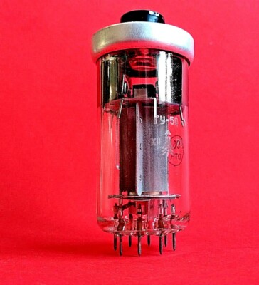
GU-50 Vacuum Tube
The Soviet GU-50, a military-grade power pentode and the direct predecessor to the FU50

The "Little 300B": Analyzing the Sonic Signature

The FU50's reputation is built largely on its performance in audio amplifiers, particularly when wired as a triode in a single-ended configuration. This is where the "little 300B" comparison originates.

The Allure of Single-Ended Class A

Most FU50 amplifiers are single-ended Class A designs. This circuit topology is revered by audiophiles for its sonic purity. In a Class A amplifier, the output tube conducts current through the entire signal cycle, resulting in very low crossover distortion. As noted by audio experts, this design often produces a high level of even-order harmonic distortion, which the human ear perceives as musically pleasing warmth and richness. This "harmonic glow" is what gives many tube amps their signature "warm, lush, and musical" sound, making vocals and acoustic instruments feel more lifelike.

How Does It Really Sound?

User reviews and expert opinions paint a consistent picture of the FU50's sound. It's often described as having a "sweet and full warm vocal flavor." An amplifier from IWISTAO is praised for its ability to produce a sound that is "pure and delicate," with a "very strong tube taste."

However, it's not just about warmth. One experienced user on a diyAudio forum offered a compelling counterpoint, describing their FU50 amp in the highest terms of neutrality:

Like all the best amps I have ever listened to, built and/or owned, it recedes into the background. It has no character... One simply listens to the music – the amp does not “impress” the listener at all.

This suggests that while the FU50 can deliver classic tube warmth, it can also achieve a high degree of transparency, allowing the music to speak for itself without excessive coloration.

The 300B Comparison: Hype vs. Reality

The "little 300B" nickname stems from the claim that the FU50';s characteristic curves, when operated in triode mode, are very similar to those of the legendary Western Electric 300B. But does it truly measure up?

According to a detailed review on the Cheaptubeaudio blog, the FU50 gets remarkably close for its price. The reviewer notes that while a good 300B amplifier still possesses a more "organic and luscious" and "tonally sophisticated" sound, the FU50 is a formidable contender. It delivers a level of finesse that can outshine other budget single-ended amps based on tubes like the EL34 or 6L6. While it may not have the same power reserve or benign clipping characteristics as a true 300B, its performance-to-price ratio is almost unbeatable.

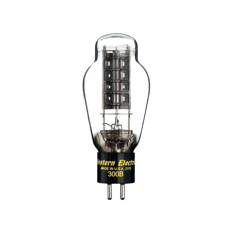
Western Electric 300B Tube
The legendary Western Electric 300B, the benchmark against which the FU50 is often compared

Anatomy of an FU50 Amplifier: Design and Circuitry

The appeal of FU50 amplifiers goes beyond their sound; their design, accessibility, and the culture around them are key parts of their story.

Common Circuit Topologies

Most FU50 amps use a single-ended circuit where the pentode FU50 is wired to operate as a triode. The choice of driver tube is a key design variation. Many kits and finished amps use the Soviet 6J8P (a pentode equivalent to the American 6SJ7) as a driver. This is significant because, as the Cheaptubeaudio review points out, this configuration bears a resemblance to the classic Western Electric 91A circuit, which famously used a pentode to drive the 300B triode. Another common option is the 6N8P (a double-triode equivalent to the 6SN7), which offers a different sonic flavor.

The DIY Spirit and Kit Culture

A major factor in the FU50's popularity is its embrace by the Do-It-Yourself (DIY) community. Thanks to the availability of inexpensive tubes and transformers from Chinese sources, building an FU50 amplifier is a highly accessible project. Brands like "Dragon & Phoenix" offer complete kits that include all parts and circuit diagrams.

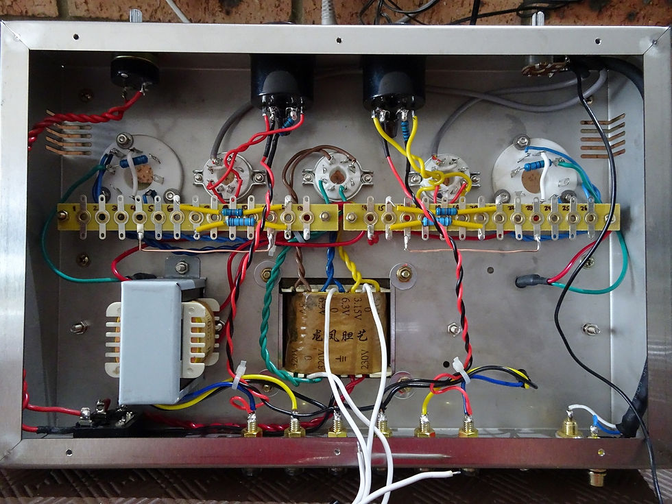
Building from a kit can be a rewarding experience, but it's not without challenges. DIY builders often report needing to troubleshoot issues like transformer hum, which typically requires careful implementation of grounding techniques, such as a proper star earth ground, to resolve. The satisfaction of building your own high-quality tube amp, however, is a powerful motivator for many enthusiasts.

Internal wiring of a FU50 tube amplifier kit
The intricate hand-wired interior of a "Dragon & Phoenix" FU50 amplifier kit, showcasing the complexity of a DIY build

Build Quality and Features

While DIY is a popular route, many commercially available FU50 amplifiers offer impressive build quality that belies their modest price. Reviewers frequently praise the "fabulous" construction of models like the BRZ FU-50, highlighting its luxurious milled aluminum chassis that surpasses many more expensive "high-end" offerings. These amplifiers are not just bare-bones circuits; modern designs often incorporate a range of features, including multiple switchable inputs for CD players, USB DACs, and even MM phono stages for turntables, making them versatile hubs for a complete audio system.

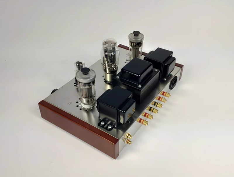
A finished FU50 tube amplifier
A finished FU50 amplifier, showcasing the high-quality build with a polished top plate and wooden side panels often found in commercial models

Getting the Most Out of Your FU50 Amp

To unlock the full potential of an FU50 amplifier, two factors are critical: speaker matching and tube selection.

The Importance of Speaker Matching

FU50 amplifiers are low-power devices, typically delivering between 8 to 13 watts per channel. This makes speaker pairing crucial. They perform best with high-sensitivity speakers (generally rated at 90 dB/watt or higher). Efficient speakers allow the amplifier to reach satisfying listening levels without being pushed into distortion. In contrast, power-hungry, low-sensitivity speakers are better suited for high-power solid-state amplifiers that can provide the necessary current and control.

Tube Rolling for Sonic Tweaks

"Tube rolling," or swapping out stock tubes for different, often vintage, alternatives, is a popular way to customize an amplifier';s sound. With an FU50 amp, changing the rectifier and driver tubes can yield significant sonic improvements. For instance, the Cheaptubeaudio review noted that replacing the stock Chinese 5Z4 rectifier with a vintage Chatham 5R4WGA resulted in a sweeter, more detailed sound. Similarly, swapping the stock FU-50 tubes for older Soviet-made versions can enhance texture and dynamics. This ability to tweak and refine the sound is a huge part of the appeal for tube enthusiasts.

Conclusion: The Verdict on the FU50 Amplifier

The FU50 amplifier is a remarkable paradox: a piece of Cold War military technology that has become a symbol of accessible, high-fidelity audio. It may not dethrone the legendary 300B, but the "little 300B" moniker is more than just marketing hype—it's a testament to the incredible sonic value this tube delivers.

For the budget-conscious audiophile, the DIY enthusiast, or anyone with efficient speakers looking for an entry point into the magical world of single-ended tube sound, the FU50 amplifier is an outstanding choice. It offers a listening experience that is pure, engaging, and deeply musical, proving that great sound doesn't always have to come with a high price tag. It has rightfully earned its place as a beloved champion in the global Hi-Fi community.

References

[2]
[4]
[5]
[6]
Fu-50 2*12w (rms) 6j8p Fu50 Tube Amplifier Stereo Single-ended ...
https://www.aliexpress.com/i/32982589478.html
[8]
Mid Trajectory 6J4/6P3P Preamp Beydas LS3/5A Clone Canare ...
https://cheaptubeaudio.blogspot.com/2022/12/mid-trajectory-6j46p3p-preamp-beydas.html
[11]
An Audio Amplifier Design Philosophy - Meta-Gizmo
https://www.meta-gizmo.org/tri/otlology/BERNINGS.htm

Wednesday, July 30, 2025

Mastering the Build: How to Design a Bass-Reflex Speaker for Your Full-Range Driver

Mastering the Build: How to Design a Bass-Reflex Speaker for Your Full-Range Driver

Mastering the Build: How to Design a Bass-Reflex Speaker for Your Full-Range Driver

Introduction: The Pursuit of Sonic Purity with Full-Range Drivers

In the world of high-fidelity audio, there exists a dedicated group of enthusiasts who champion a seemingly simple component: the full-range driver. Their appeal is undeniable. By using a single driver to reproduce the entire audible frequency spectrum, they eliminate the need for complex crossover networks that can introduce phase shifts and other distortions. The result is a coherent, point-source soundstage often described as "magical," "holographic," or possessing an openness and directness that multi-way systems can struggle to replicate.

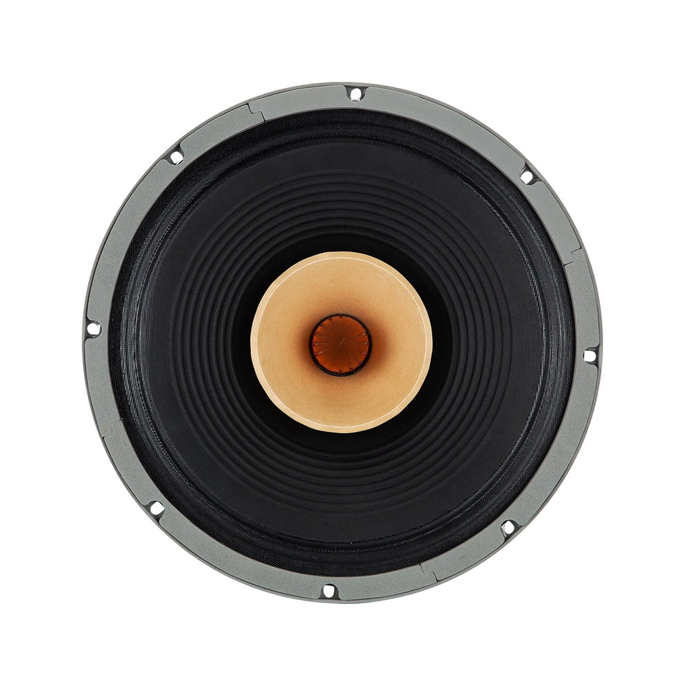
A full-range speaker driver
A high-quality full-range driver, the heart of a point-source audio system

However, this sonic purity comes with a challenge. Physics dictates that a single cone struggles to reproduce the thunderous lows of a bass guitar and the delicate highs of a cymbal with equal authority. While many full-range drivers excel in the midrange, their low-frequency output can be limited. To unlock their full potential, especially in the bass department, a driver needs the right home: a carefully designed enclosure.

This is where the bass-reflex, or ported, enclosure comes in. It is a popular and highly effective method for extending a driver's bass response and improving its overall efficiency. By cleverly using the sound energy from the back of the cone, a bass-reflex design can help a modest full-range driver produce a surprisingly deep and powerful low end.

This article serves as a comprehensive, step-by-step guide for the DIY audio enthusiast. We will demystify the essential Thiele-Small (T/S) parameters and show you how to use them to design a custom bass-reflex enclosure tailored specifically to your full-range driver. By the end, you'll have the knowledge to move beyond guesswork and engineer a speaker that is a true marriage of science and sound, complete with a detailed, practical example to guide your build.

The Blueprint: Understanding Key Thiele-Small (T/S) Parameters

Before we can build a house, we need a blueprint. In speaker design, that blueprint is the driver's Thiele-Small (T/S) parameters. These are a set of electromechanical specifications that precisely describe a driver's behavior. Named after Australian engineers A. Neville Thiele and Richard H. Small, their work in the 1960s and 70s revolutionized loudspeaker design, transforming it from a trial-and-error art into a predictable science. As Audiophonics notes, these parameters are invaluable as they provide detailed information on the behavior and actual performance of a loudspeaker.

Understanding these parameters is not just academic; it is the fundamental requirement for designing any enclosure, especially a tuned system like a bass-reflex box. Without them, as Audio Judgement puts it, "you are blindfolded." Let's break down the most critical parameters for our task.

Core Parameters for Bass-Reflex Design

While a driver's spec sheet may list a dozen or more parameters, only a few are essential for the initial design of a bass-reflex enclosure.

  • Fs (Free Air Resonance): Measured in Hertz (Hz), this is the natural frequency at which the driver's moving parts (cone, voice coil) resonate when suspended in free air, without an enclosure. It';s determined by the moving mass (Mms) and the suspension's compliance (Cms). A lower Fs generally indicates the driver has the potential to produce deeper bass frequencies. As a rule of thumb, a woofer with an Fs of 30 Hz will struggle to play frequencies significantly below that point.
  • Qts (Total Q): This unitless parameter is arguably the most important for determining a driver's suitability for a particular enclosure type. It represents the driver's total damping at its resonant frequency (Fs), combining both its mechanical (Qms) and electrical (Qes) damping. The value of Qts acts as a powerful guide:
    A general rule of thumb, supported by numerous sources like Audiophonics and DIY forums, is that a Qts lower than or equal to 0.4 is often ideal for a vented (bass-reflex) enclosure. A Qts between 0.4 and 0.7 is typically better suited for a sealed enclosure, and values above 0.7 may be best for open-baffle or free-air applications.
  • Vas (Equivalent Compliance Volume): Expressed in liters or cubic feet, Vas represents a volume of air that has the same compliance (springiness) as the driver's own suspension (surround and spider). It's a measure of the suspension's stiffness. A driver with a "loose" suspension will have a high Vas, while one with a "stiff" suspension will have a low Vas. This parameter is a key variable in the formula for calculating the final enclosure volume (Vb). As BCAE1 explains, speakers with a loose suspension and high Vas tend to require larger enclosures.

Supporting Parameters

While the three parameters above are the primary inputs for our calculations, a few others provide important context and help in refining the design.

  • Sd (Piston Area): The effective surface area of the driver's cone, usually measured in square centimeters (cm²). This tells you how much air the driver can move.
  • Xmax (Maximum Linear Excursion): Measured in millimeters (mm), this indicates how far the cone can travel in one direction from its resting position while maintaining linear behavior. A higher Xmax generally means the driver can play louder at low frequencies with less distortion.
  • Re (DC Resistance): The DC resistance of the voice coil, measured in Ohms (Ω). It will always be slightly lower than the driver's nominal impedance (e.g., an 8Ω speaker might have an Re of 6.5Ω).
  • Qes (Electrical Q): A component of Qts, this measures the damping provided by the speaker';s "motor" system (the magnet and voice coil). It's a critical value used in a quick check to determine enclosure suitability.

The Science of Sound: Bass-Reflex Fundamentals

Now that we have our blueprint (the T/S parameters), let's understand the architectural principles of the structure we're building. A bass-reflex enclosure is more than just a box with a hole in it. That "hole," correctly termed a port or vent, is a precisely engineered element that turns the entire enclosure into a tuned acoustic system.

How It Works: The Helmholtz Resonator

The core principle behind a bass-reflex speaker is the Helmholtz resonator, a concept dating back to the 1850s. Imagine blowing across the top of a bottle to create a tone. The bottle's cavity (the air inside) and its neck form a resonator. In a speaker, the enclosure's internal volume is the "cavity," and the port is the "neck."

When the speaker cone moves backward into the enclosure, it pressurizes the air inside. In a sealed box, this trapped air acts like a spring, pushing back on the cone. In a bass-reflex box, this pressure escapes through the port. The air within the port has mass, and the air inside the box has springiness. Together, they form a resonant system. By carefully choosing the enclosure volume and the port's dimensions (length and diameter), we can "tune" this system to a specific frequency (Fb).

At and around this tuning frequency, the sound wave emerging from the port is in phase with the sound wave coming from the front of the speaker cone. The two waves reinforce each other, leading to a significant boost in output at that frequency range. As Audio Intensity explains, this resonance is the key to the enhanced bass response.

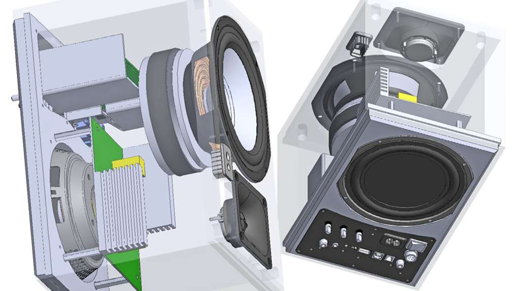
Cutaway view of a bass-reflex speaker enclosure
A 3D rendering showing the internal structure, driver, and bracing of a bass-reflex enclosure

Key Advantages

When designed correctly, a bass-reflex system offers several compelling benefits over its sealed counterpart:

  • Extended Low-Frequency Response: The primary goal. A ported box can achieve a lower cutoff frequency (f3, the point where bass output is down by 3 dB) than a sealed box of a similar size, effectively extending the frequency response.
  • Increased Efficiency: Around the tuning frequency, the port's output adds to the driver';s, resulting in a sensitivity boost of up to 3 dB. This means you get more bass for the same amount of amplifier power, a significant advantage for lower-powered amplifiers often paired with full-range drivers.
  • Reduced Cone Excursion: At the tuning frequency, the port is doing most of the work. The air in the port provides a high acoustic load on the driver, drastically reducing the cone's movement. This leads to lower distortion and increased power handling at those critical low frequencies.

Potential Downsides

The benefits of a bass-reflex design come with trade-offs that must be managed:

  • Transient Response: The resonant nature of the system can sometimes lead to a slightly less ";tight" or ";articulate" bass compared to the crisp response of a well-designed sealed enclosure. This is often described as group delay, where bass notes can sound slightly smeared or "slower."
  • Port Noise: If the port is too small for the amount of air being moved, turbulence can occur, creating an audible "chuffing"; or "whistling" sound, especially at high volumes. Proper port sizing is crucial to avoid this.
  • Steeper Roll-off: Below the tuning frequency, the output from the port begins to move out of phase with the driver, causing cancellation. This results in a much faster drop-off in bass response, typically at 24 dB per octave, compared to the gentler 12 dB per octave slope of a sealed box.

The Core Task: A Step-by-Step Guide to Enclosure Design

This section is the heart of our project. Here, we translate theory into practice, using the driver's T/S parameters to calculate the three critical values for our enclosure: the internal volume (Vb), the tuning frequency (Fb), and the port dimensions. This process, once understood, is a repeatable method for any bass-reflex design.

Step 1: Choose Your "Alignment" - Defining the Sound Character

The first and most crucial decision is selecting an "alignment." In this context, an alignment is not a physical adjustment but a standardized design target. As audioXpress explains, Thiele's genius was recognizing that a speaker system's acoustic response is analogous to an electrical high-pass filter. By designing the box to match a known filter characteristic (like Butterworth or Bessel), its performance becomes predictable.

The choice of alignment dictates the trade-offs between bass extension (how low it goes), frequency response flatness (absence of peaks or dips), and transient response (how ";fast" and "tight" the bass sounds). The driver's Qts is the primary factor determining which alignments are achievable.

A Quick Check: Efficiency Bandwidth Product (EBP)

Before diving into alignments, a simple calculation called the Efficiency Bandwidth Product (EBP) can give a strong indication of whether your driver is a good candidate for a ported box. The formula is:

EBP = Fs / Qes

A widely accepted guideline, mentioned on sites like Audiophonics, is:

  • EBP near 100 (or higher): The driver is generally well-suited for a bass-reflex enclosure.
  • EBP near 50 (or lower): The driver is likely a better candidate for a sealed enclosure.
  • Values in between: The driver may work well in either type of enclosure, making the choice dependent on design goals.

Common Alignments for DIY

There are many alignments, but a few are particularly popular and effective for DIY projects:

  • Butterworth (B4): Often considered the standard for a ";maximally flat" response. It provides excellent bass extension with no peak in the frequency response, offering a very balanced sound. However, it is a "discrete" alignment, meaning it's only achievable with a driver that has a very specific Qts, typically around 0.38 to 0.40.
  • Quasi-Butterworth (QB3/SBB4): This is a highly flexible and popular family of alignments. As detailed in an article by Audio Judgement, alignments like QB3 (Quasi-3rd-order Butterworth) and SBB4 (Sub-Boom-Box) work for a wider range of Qts values (often 0.2 to 0.4). They provide an excellent balance of good bass extension and reasonable box size, making them a go-to for many designers.
  • Bessel (BE4): This alignment prioritizes transient response above all else. It yields the tightest, most articulate bass with minimal group delay. The trade-off is that it has less low-frequency extension compared to a Butterworth alignment. Like the B4, it is a discrete alignment requiring a specific Qts (around 0.33).
A comparison of typical low-frequency roll-off curves for Sealed, Butterworth, and Bessel alignments, showing the deeper extension of the B4 at the cost of a steeper slope.

Step 2: Calculate Enclosure Volume (Vb) and Tuning Frequency (Fb)

Once you've chosen an alignment, the math is surprisingly straightforward. The calculations rely on two key ratios, `α` (alpha) and `H`, which are derived from complex filter theory but are readily available in published alignment tables or from speaker design software.

The core formulas are:

Vb = Vas / α
Fb = H * Fs

Where:

  • Vb is the net internal volume of the enclosure.
  • Fb is the Helmholtz resonance (tuning frequency) of the enclosure.
  • Vas and Fs are the parameters from your driver's spec sheet.
  • α (alpha) is the system compliance ratio.
  • H is the tuning ratio.

The process is simple: find a reliable source for alignment tables (like those in Vance Dickason's "Loudspeaker Design Cookbook" or provided by online calculators). Look up your chosen alignment (e.g., QB3) and find the row that corresponds to your driver's Qts. That row will give you the necessary `α` and `H` values to plug into the formulas. As audioXpress points out, these two normalized parameters are all you need to start defining the physical box.

Step 3: Calculate Port Dimensions

With the box volume (Vb) and tuning frequency (Fb) determined, the final step is to design a port that will achieve that tuning. This involves choosing a port area and then calculating the required length.

Port Area and Shape

The area of the port is critical. If it's too small, the air velocity inside can become excessive at high volumes, leading to compression (the port can't move enough air) and audible noise (chuffing). A common rule of thumb is to start with a port area that is between 1/3 and 1/2 of the driver's effective piston area (Sd). Ports can be round (often made from PVC pipe) or rectangular/slot-shaped (built from the same material as the enclosure). Both are acoustically effective, though round ports with flared ends are often preferred to minimize turbulence.

Port Length Formula

The length of the port is inversely proportional to the box volume and the square of the tuning frequency. There are many variations of the formula, but a standard one for a single, round port is:

Lv = ( (23562.5 * D^2) / (Fb^2 * Vb) ) - (0.732 * D)

Where:

  • Lv is the length of the port in centimeters.
  • D is the inner diameter of the port in centimeters.
  • Fb is the tuning frequency in Hz.
  • Vb is the net box volume in liters.

Note: This formula includes an "end correction" factor (the `0.732 * D` part), which accounts for the fact that the air just outside the port openings also behaves as part of the moving mass.

Practical Trade-offs

You will quickly discover a fundamental trade-off in port design. For a given tuning, a larger diameter port (which is better acoustically) requires a much longer length. A smaller diameter port can be very short but is more prone to noise. Sometimes, the calculated port length is too long to physically fit inside the enclosure. In such cases, the designer must compromise: either accept a smaller, potentially noisier port, or reconsider the enclosure tuning or volume. This is a key challenge in designing small, low-tuned speakers, as explored in an example by audioXpress.

Putting It All Together: A Practical Design Example

Theory is essential, but a practical example makes the concepts concrete. Let's walk through the entire design process for a hypothetical—but realistic—full-range driver to see how these numbers translate into a real-world speaker design.

1. The Driver: "The Audiophile's Choice FC8"

Imagine we have purchased a promising 8-inch full-range driver. After consulting the manufacturer's specification sheet, we have the following key Thiele-Small parameters:

  • Fs (Free Air Resonance): 45 Hz
  • Qts (Total Q): 0.38
  • Vas (Equivalent Compliance Volume): 28 Liters
  • Qes (Electrical Q): 0.41
  • Sd (Piston Area): 210 cm²

2. Choose the Alignment

Our first step is to determine the best enclosure type and alignment.

First, we run the EBP check:

EBP = Fs / Qes = 45 Hz / 0.41 ≈ 109.8

With an EBP well over 100, this driver is an excellent candidate for a bass-reflex enclosure.

Next, we select the alignment based on Qts:

The driver's Qts is 0.38. This is right in the sweet spot for a Butterworth (B4) alignment. We'll choose this target because it promises a maximally flat frequency response, which is a great goal for a high-fidelity system.

3. Calculate Box Volume and Tuning

Now we consult a B4 alignment table (or use a tool like WinISD). For a driver with a Qts of 0.38, the standard B4 alignment parameters are:

  • α (alpha): ≈ 1.4
  • H: ≈ 1.0

With these ratios, we can calculate our target volume and tuning frequency:

Enclosure Volume (Vb):

Vb = Vas / α = 28 Liters / 1.4 = 20 Liters

Tuning Frequency (Fb):

Fb = H * Fs = 1.0 * 45 Hz = 45 Hz

So, our design target is a 20-liter enclosure tuned to 45 Hz.

4. Calculate Port Dimensions

The final step is to design a port that will tune our 20-liter box to 45 Hz.

First, choose a port diameter. A good starting point is a port with an area of about 1/4 to 1/3 of Sd. Our Sd is 210 cm². Let's aim for an area around 50-70 cm². A 3-inch (7.62 cm) diameter port has an area of about 45 cm², which is a bit small. A 4-inch (10.16 cm) port has an area of 81 cm², which is better. Let's try a more common size in between: a 3-inch internal diameter (D = 7.62 cm) port.

Now, calculate the required length (Lv) using our formula:

Lv = ( (23562.5 * D²) / (Fb² * Vb) ) - (0.732 * D)

Lv = ( (23562.5 * 7.62²) / (45² * 20) ) - (0.732 * 7.62)

Lv = ( (23562.5 * 58.06) / (2025 * 20) ) - 5.58

Lv = (1368209.5 / 40500) - 5.58

Lv = 33.78 cm - 5.58 cm ≈ 28.2 cm

A length of 28.2 cm (about 11.1 inches) is quite long but should be manageable in a box with a 20-liter volume, especially if placed diagonally.

5. Final Design Summary

  • Driver: The Audiophile's Choice FC8
  • Enclosure Type: Bass-Reflex, Butterworth (B4) Alignment
  • Internal Volume (Vb): 20 Liters (net, after accounting for driver and port displacement)
  • Tuning Frequency (Fb): 45 Hz
  • Port: One round port, 7.62 cm (3 inches) in diameter and 28.2 cm (11.1 inches) long.

Beyond the Numbers: Practical Tips for a Successful Build

The calculations provide a solid, scientific foundation for your speaker, but the final sonic result also depends on the quality of construction. Here are some practical tips to ensure your build is as successful as your design.

Enclosure Construction

  • Material Choice: The ideal cabinet material is dense, rigid, and non-resonant. Medium-Density Fiberboard (MDF) is the most common choice for DIY builders due to its high density, uniform consistency, and affordability. High-quality Baltic Birch plywood is another excellent, albeit more expensive, option. Avoid particleboard or solid wood, as they can have voids or resonate undesirably.
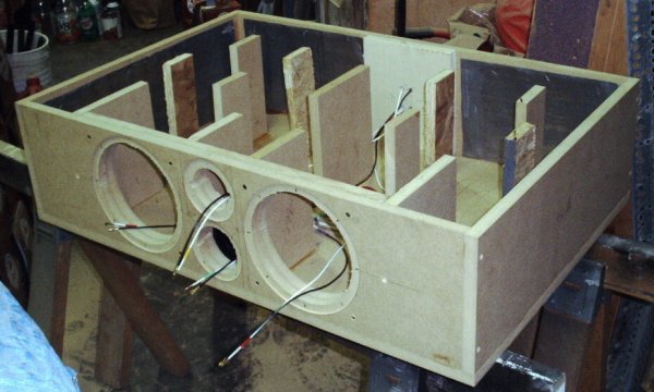
  • Bracing is Not Optional: This is one of the most overlooked aspects by beginners. Large, unbraced cabinet panels will vibrate in sympathy with the music, coloring the sound and smearing detail. As one experienced builder on a DIY Audio forum states, "Cabinet resonances are bad. Use braces." Connect opposing panels with wooden dowels or "window" braces to dramatically increase rigidity.
A DIY speaker cabinet with internal bracing
A well-constructed DIY speaker cabinet showing extensive internal bracing to reduce resonance

Acoustic Damping

Lining the internal walls of the enclosure with acoustic damping material serves a critical purpose: it absorbs high- and mid-frequency sound waves bouncing around inside the box. These internal reflections can otherwise escape through the driver cone or the port, interfering with the direct sound and reducing clarity. Common materials include:

  • Acoustic Foam: Egg-crate or convoluted foam is effective and easy to apply.
  • Poly-fil / Fiberfill: The same material used in pillows can be loosely stuffed into the enclosure.
  • Denim Insulation or Wool: Natural fibers are excellent sound absorbers.

A good practice is to line the back, top, bottom, and side walls, but be careful to keep the area immediately around the port's internal opening clear to ensure unrestricted airflow. As noted by designer Troels Gravesen, heavy damping can slightly lower the effective tuning frequency of the port.

Software and Tools

While manual calculations are great for understanding the principles, software can save time and provide deeper insights. Many free and powerful tools are available to automate the design process:

  • WinISD: A long-standing and popular freeware program for Windows. It allows you to input T/S parameters, model various alignments, and visualize the predicted frequency response, cone excursion, and port air velocity.
  • Online Calculators: Websites like SubBox.pro and SpeakerBoxLite offer web-based tools that can quickly calculate box volumes and port dimensions, often providing cutting plans as well.
  • Speakerbench: A more advanced, web-based application created by industry experts that provides highly accurate modeling for various low-frequency alignments.

Measure, Don't Guess

For the dedicated enthusiast seeking ultimate precision, it's important to know that manufacturer-provided T/S parameters can have a tolerance of +/- 10% or more. Furthermore, a driver's parameters can change slightly after a ";break-in" period. For this reason, professionals and serious hobbyists often measure the parameters of their specific drivers themselves using a tool like the Dayton Audio DATS (Dayton Audio Test System). While not essential for a first-time builder, measuring your own parameters is the definitive way to ensure your enclosure is perfectly optimized for your driver.

Conclusion: From Parameters to Performance

The journey from a raw speaker driver to a finished, high-performance audio system is a deeply rewarding one. We've seen how a handful of numbers—the Thiele-Small parameters—can serve as a reliable blueprint, guiding us through the complexities of acoustic design. By understanding the fundamental principles of the bass-reflex system and methodically applying proven alignment theories, we can move beyond guesswork and engineer an enclosure that is scientifically tailored to extract the very best performance from a full-range driver.

We've demystified the process: starting with the driver's "DNA" (Fs, Qts, Vas), choosing a sonic character through an alignment (like the flat response of a B4), and translating those targets into physical dimensions for the enclosure volume (Vb) and port. Our practical example demonstrated that with a few key formulas and a clear process, anyone can design a speaker with predictable and excellent results.

Ultimately, building your own speaker is a beautiful fusion of science and craft. The math provides the solid foundation, ensuring the acoustic principles are sound. The craftsmanship in construction—the rigid, well-braced cabinet and careful assembly—brings that design to life. The satisfaction of listening to a speaker you not only built but also designed, one that produces a coherent, detailed, and surprisingly deep soundstage, is an experience unmatched in the world of audio.

So, gather your tools, select your driver, and start your project. Experiment with different drivers and alignments. Embrace the process of learning and creation. The world of DIY audio is waiting, and the satisfaction of building a speaker that sounds truly exceptional is your reward.

References

[1]
Thiele / Small parameters explained with real world cases
https://audiojudgement.com/thiele-small-parameters-explained/
[2]
Understanding bass-reflex technology - Blog Son-Vidéo.com
https://blog.son-video.com/en/2016/09/understanding-bass-reflex-technology/
[3]
Full List: Thiele-Small Speaker Parameters W/ Descriptions
https://mynewmicrophone.com/full-list-thiele-small-speaker-parameters-w-descriptions/
[4]
[5]
Full List: Thiele-Small Speaker Parameters W/ Descriptions
https://mynewmicrophone.com/full-list-thiele-small-speaker-parameters-w-descriptions/
[9]
Bass reflex alignments explained - Step by step - Audio Judgement
https://audiojudgement.com/bass-reflex-alignments-explained/
[10]
Bass tuning using the Thiele and Small parameters
https://www.lautsprechershop.de/hifi/inter_ps_tus_en.htm
[11]
Measuring Loudspeaker Driver Parameters - Elliott Sound Products
https://sound-au.com/tsp.htm
[12]
Acoustics/Bass-Reflex Enclosure Design - Wikibooks
https://en.wikibooks.org/wiki/Acoustics/Bass-Reflex_Enclosure_Design
[13]
Bass reflex speaker design - easy explanation - Audio Judgement
https://audiojudgement.com/bass-reflex-speaker-design/
[15]
Bass Reflex Performance Envelope - Part 3: A Practical Example
https://audioxpress.com/article/bass-reflex-performance-envelope-part-3-a-practical-example
[16]
Bass reflex speaker design - easy explanation - Audio Judgement
https://audiojudgement.com/bass-reflex-speaker-design/
[17]
Understanding bass-reflex technology - Blog Son-Vidéo.com
https://blog.son-video.com/en/2016/09/understanding-bass-reflex-technology/
[19]
[20]
[PDF] Optimal Bass Reflex Loudspeaker Port Design - COMSOL
https://www.comsol.com/paper/download/679311/bezzola_paper.pdf
[21]
The IB4 Bass Reflex Alignment - audioXpress
https://audioxpress.com/article/the-ib4-bass-reflex-alignment
[23]
Bass reflex alignments explained - Step by step - Audio Judgement
https://audiojudgement.com/bass-reflex-alignments-explained/
[24]
[25]
[PDF] Design of bass-re ex loudspeakers: the standard alignment - RiuNet
https://riunet.upv.es/bitstreams/3b906dec-0f31-493f-97c8-5b0fbdf08d20/download
[26]
Port Length and Diameter: Mastering Subwoofer Enclosures
https://proline-x.com/mastering-subwoofer-enclosures-port-length-and-diameter
[27]
Computation of Bass Reflex Alignments - audioXpress
https://audioxpress.com/article/focus-computation-of-bass-reflex-alignments
[28]
[PDF] Design of bass-re ex loudspeakers: the standard alignment - RiuNet
https://riunet.upv.es/bitstreams/3b906dec-0f31-493f-97c8-5b0fbdf08d20/download
[30]
Computation of Bass Reflex Alignments - audioXpress
https://audioxpress.com/article/focus-computation-of-bass-reflex-alignments
[31]
Bass Reflex Alignments: Compliance Alteration - audioXpress
https://audioxpress.com/article/bass-reflex-alignments-compliance-alteration
[32]
[PDF] Maximizing Bass Reflex System Performance Through Optimization ...
https://stars.library.ucf.edu/cgi/viewcontent.cgi?article=1956&context=honorstheses
[33]
SpeakerBoxLite. Subwoofer box calculator, Sub box calculator
https://speakerboxlite.com/
[35]
[PDF] low frequency group delay equalization of vented boxes using
https://www.dafx.de/paper-archive/2014/dafx14_stephan_herzog_low_frequency_group_delay.pdf
[36]
Bass Reflex Performance Envelope - Part 3: A Practical Example
https://audioxpress.com/article/bass-reflex-performance-envelope-part-3-a-practical-example
[37]
Bass reflex port calculation - DIY Audio Projects - StereoNET
https://www.stereonet.com/forums/topic/463117-bass-reflex-port-calculation/
[38]
[41]
[42]
Subwoofer Enclosure Calculators, Parallel, Series, Port Length and ...
https://www.the12volt.com/caraudio/boxcalcs.asp
[44]
Bass reflex alignments explained - Step by step - Audio Judgement
https://audiojudgement.com/bass-reflex-alignments-explained/