Monday, July 14, 2025

A Guide to Power Amplifier Distortion and Mitigation Techniques

A Guide to Power Amplifier Distortion and Mitigation Techniques


 Published by IWISTAO

In the world of audio, achieving a pure, unaltered sound is the ultimate goal. However, as a signal passes through a power amplifier, it is susceptible to various forms of distortion. This article, based on detailed analysis of audio amplifier principles, explores the common types of distortion, their causes, and effective methods for their improvement. We will cover both classic analog distortions and modern digital solutions.

Distortion can be broadly categorized into two types: linear and non-linear. Linear distortion alters the amplitude and phase of different frequency components without adding new ones, while non-linear distortion introduces new frequency components, resulting in a harsh and unnatural sound. 


1. Harmonic Distortion (THD)

Harmonic Distortion is one of the most fundamental types of non-linear distortion, occurring when the amplifier's non-linear components create harmonics (multiples) of the original input frequency.

Characteristics

Total Harmonic Distortion (THD) is measured as the ratio of the sum of the powers of all harmonic components to the power of the fundamental frequency. A lower THD value indicates better performance. While a THD below 0.1% is generally imperceptible to the human ear, the character of the harmonics matters significantly.

  • Odd-order harmonics (3rd, 5th, etc.), common in solid-state ("stone") amplifiers, are often perceived as harsh and unpleasant.
  • Even-order harmonics (2nd, 4th, etc.), prevalent in tube ("valve") amplifiers, tend to sound more musical and warm, which is why some listeners prefer the "tube sound" even if the measured THD is higher.

It's crucial to note that THD specifications should always include measurement conditions (e.g., output power), as a low THD at 1W doesn't guarantee low distortion at higher power levels.


Mitigation Methods

  • Apply appropriate voltage or current negative feedback.
  • Use high-performance amplifying components with good linearity and high transition frequency (fT).
  • Ensure high consistency of matched pairs of transistors in circuit stages.
  • Employ Class-A amplification, known for its superior linearity.
  • Improve the power supply by increasing its power reserve and enhancing its filtering performance.


2. Intermodulation Distortion (IMD)

IMD occurs when two or more signals of different frequencies are amplified simultaneously, causing them to modulate each other and create new, non-harmonically related frequencies (sum and difference tones).

Characteristics

Unlike harmonic distortion, IMD products are not musically related to the original signal. This makes them easily detectable and particularly jarring to the human ear, often described as "harsh" or "piercing." IMD can reduce the clarity and sense of layering in the soundstage. For Hi-Fi amplifiers, an IMD of less than 0.1% is desirable.

Mitigation Methods

  • Use electronic crossover networks to limit the bandwidth of each amplifier channel or speaker driver.
  • Install a high-pass filter at the input to eliminate sub-low frequencies that can cause IMD.
  • Select components and circuit topologies known for good linearity.


3. Transient Distortion

Transient distortion relates to an amplifier's inability to accurately follow rapid, sudden changes in the input signal, such as the strike of a drum or a cymbal crash. It is a critical dynamic performance indicator.

A. Transient Intermodulation Distortion (TIM)

TIM, sometimes called "slew-induced distortion," was identified in the 1970s as a major culprit behind the harsh "transistor sound" of early solid-state amplifiers. 

Characteristics

It occurs in amplifiers with high levels of negative feedback. When a fast-rising signal is applied, the feedback loop cannot respond instantly due to propagation delays. For a moment, the amplifier operates in an open-loop state, causing the input stage to overload and clip. This momentary clipping generates a burst of high-frequency distortion.

Mitigation Methods

  • Limit the open-loop gain and the amount of negative feedback.
  • Use high-speed transistors (high fT) to reduce propagation delays.
  • Cancel the main feedback loop and rely on local feedback within each stage.
  • Use a leading (phase-advance) compensation network instead of a lagging one.
  • Increase the static current of the input stage to improve its dynamic range.

B. Slew Rate Induced Distortion

Slew Rate (SR) measures the maximum rate of change of an amplifier's output voltage, typically expressed in volts per microsecond (V/μs). If the input signal changes faster than the amplifier's slew rate, the output cannot keep up, resulting in a distorted, triangular-shaped waveform instead of the intended sine wave.

Characteristics

An amplifier with a high slew rate offers better resolution, layering, and positioning, especially with dynamic music. However, an excessively high slew rate can lead to instability and oscillation.

Mitigation Methods

  • Employ ultra-high-speed, low-noise transistors in the amplifier's design.
  • Ensure the slew rate of the preamplifier stage does not exceed that of the power amplifier stage to prevent TIM.


4. Other Common Distortions

Crossover Distortion

This occurs in Class-B and Class-AB push-pull amplifiers. It';s a non-linearity that happens around the zero-crossing point where one transistor turns off and the other turns on. It is most noticeable at low volumes and generates high-order harmonics. The primary solution is to apply a small amount of bias current to the output transistors (moving into Class-AB operation) to ensure a smooth transition.

Clipping Distortion

Clipping happens when the amplifier is driven beyond its maximum output voltage or current capabilities. The peaks of the waveform are "clipped" off, creating a square-like wave. This not only sounds harsh but also generates a large amount of high-frequency energy that can damage tweeters.

AC Interface Distortion

This is caused by the back electromotive force (EMF) from the speaker's voice coil movement, which feeds back into the amplifier's output and can interfere with its operation. Mitigation methods include using a well-designed power supply, selecting speakers with a suitable impedance curve, and ensuring a proper damping factor.


5. Modern Linearization Techniques

While the classic techniques above are fundamental to good analog design, modern systems, especially in wireless communications, rely on advanced digital signal processing (DSP) to enhance linearity and efficiency.

Power Back-off

The simplest way to ensure linearity is to operate the amplifier well below its maximum power capability (saturation point). This is known as power back-off. While effective, it comes at a significant cost to power efficiency, as much of the energy is dissipated as heat. 


The trade-off between power efficiency and output power. Power back-off is required to maintain linearity, but it reduces efficiency.


Digital Predistortion (DPD)

DPD is a powerful technique that has become essential in modern RF systems like 5G and Wi-Fi. It works by intentionally distorting the input signal in a way that is the inverse of the amplifier';s distortion characteristic. When this pre-distorted signal passes through the amplifier, the amplifier's non-linearity cancels out the pre-distortion, resulting in a clean, linear output. 

DPD models, often based on mathematical frameworks like the Generalized Memory Polynomial (GMP), can correct for both non-linearities and memory effects (where the amplifier';s behavior depends on past signals). This allows the amplifier to be operated closer to its saturation point, achieving both high linearity and high efficiency. More advanced DPD systems even use deep learning and neural networks for more accurate modeling. 


Other Advanced Techniques

Several other linearization methods exist, each with its own trade-offs:

  • Feedforward: This technique samples the amplifier's output, subtracts the original input to isolate the distortion, and then injects an anti-phase version of this distortion signal back into the output to cancel it. It is very effective and stable but can be complex and costly.
  • Feedback: This involves wrapping a feedback loop around the amplifier to correct errors. While common in audio (as negative feedback), its bandwidth is often limited in high-frequency RF applications.

A comprehensive overview of these techniques can be found in academic papers and industry reviews. 


Reference

[1]
Distortion In Power Amplifiers - Douglas Self
http://douglas-self.com/ampins/dipa/dipa.htm
[2]
Nonlinear Distortion - an overview | ScienceDirect Topics
https://www.sciencedirect.com/topics/engineering/nonlinear-distortion
[3]
Synergistic Approaches for Mitigation of Harmonic Distortion in …
https://ijereee.com/article/1%20May%202025%20IJEREEE.pdf
[4]
Selecting Capacitors to Minimize Distortion in Audio Applications
https://www.ti.com/lit/pdf/slyt796
[5]
A review on harmonic elimination and mitigation techniques in power …
https://www.sciencedirect.com/science/article/pii/S0378779624004590
[6]
Maximize Linearity in Amplifiers: Techniques with Transistors
https://www.infotransistor.com/maximize-linearity-in-amplifiers-techniques-with-transistors/
[7]
How to Improve Power Amplifier Linearity | Keysight
https://www.keysight.com/us/en/use-cases/improve-power-amplifier-linearity.html
[8]
Intermodulation Distortion in Active and Passive …
https://research.chalmers.se/publication/536155/file/536155_Fulltext.pdf
[9]
Optimization Techniques for Critical Issues in Power …
https://link.springer.com/content/pdf/10.1007/978-981-96-3216-9_3
[10]
Linear Distortion - an overview | ScienceDirect Topics
https://www.sciencedirect.com/topics/engineering/linear-distortion
[11]
[14]
Linearization as a Solution for Power Amplifier …
https://www.mdpi.com/2079-9292/10/9/1073
[15]
Enhancing Power Amplifier Linearity Via Hybrid Power Back …
https://ieeexplore.ieee.org/document/11035054
[16]
AES Journal Forum » Distortion Correction in Audio Power Amplifiers
https://secure.aes.org/forum/pubs/journal/?elib=3935
[17]Power Amplifier Linearization Techniques: An Overview

Thursday, July 10, 2025

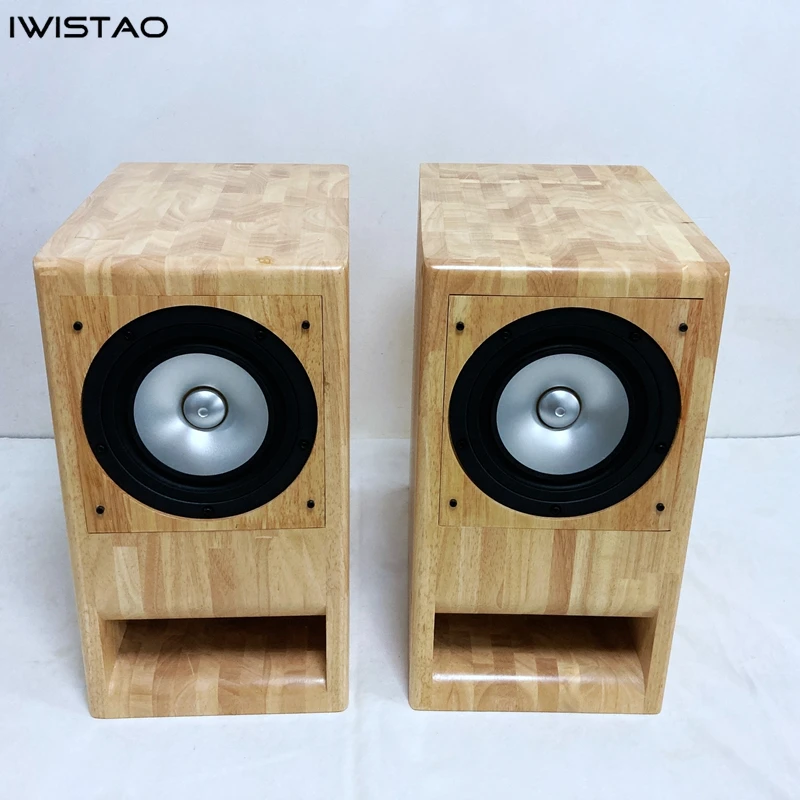
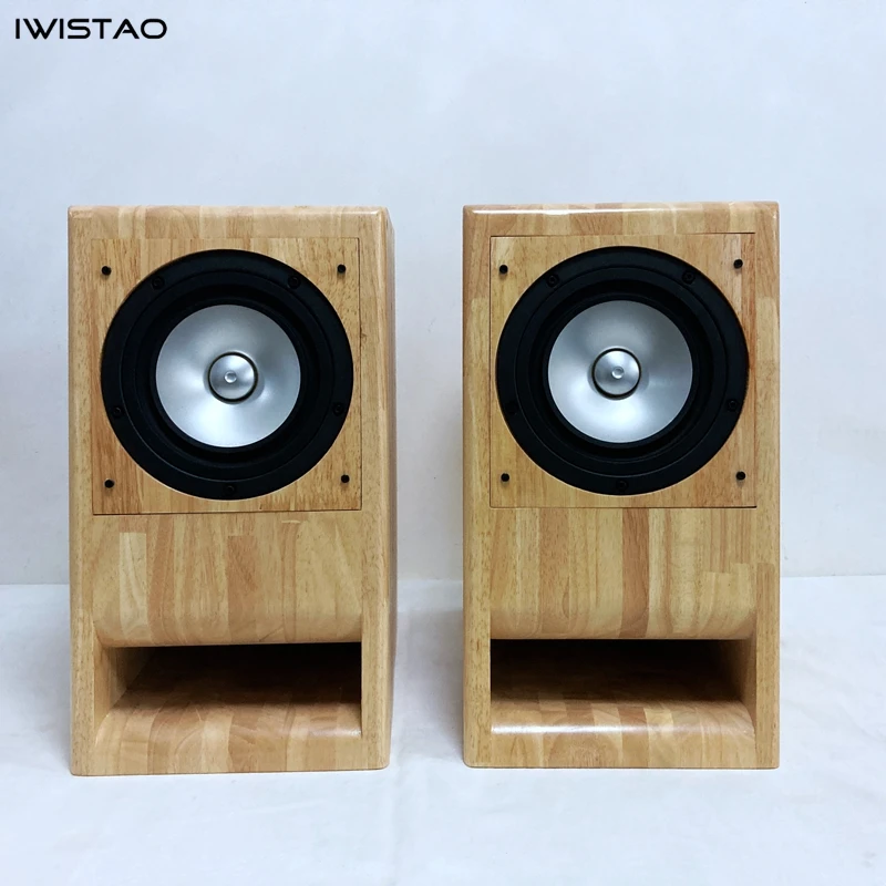
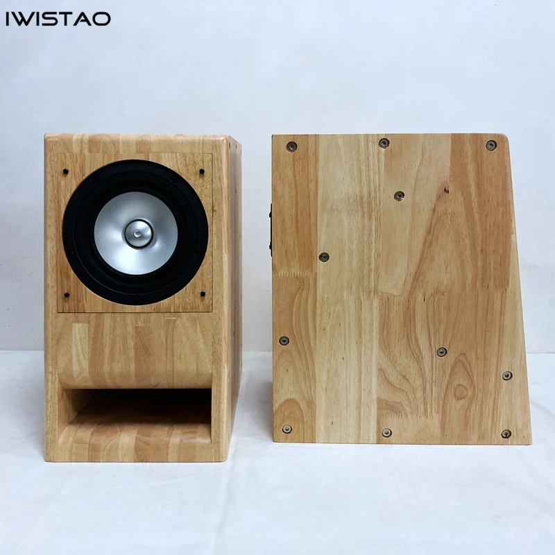
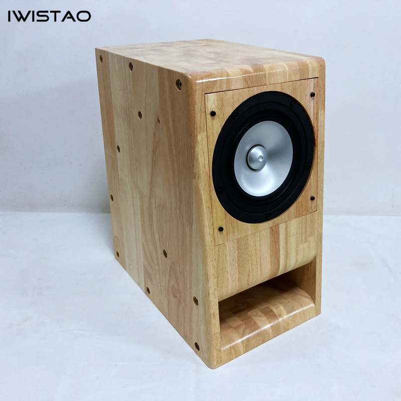
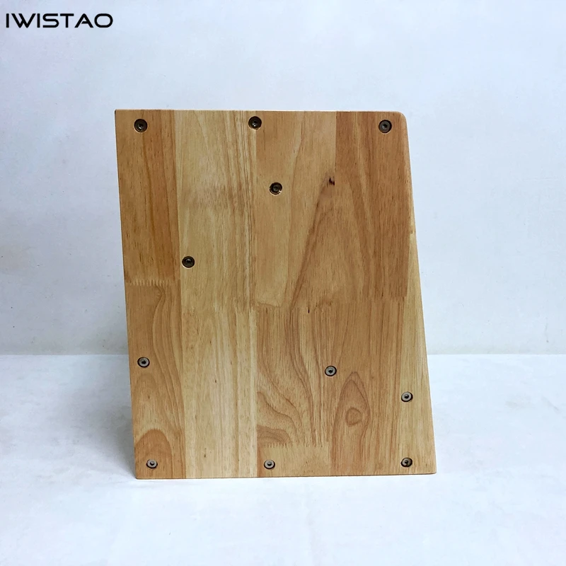
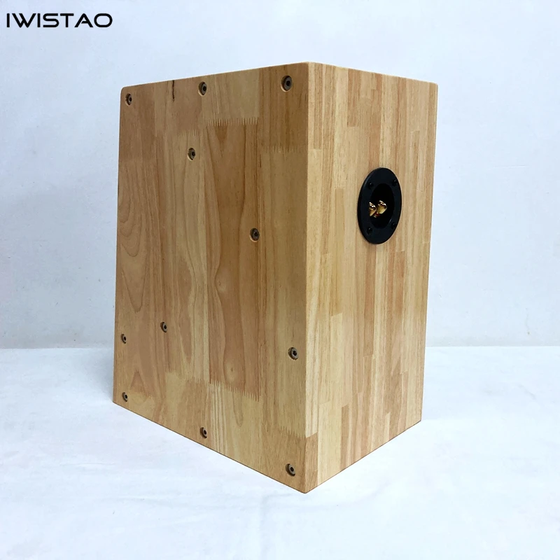
IWISTAO 8 Inch Transmission Liine Finished Speaker Solid wood with Mark 8 Inch Full Speaker Unit

IWISTAO 8 Inch Labyrinth Finished Speaker Solid wood with Mark 8 Inch Full Speaker Unit


Speaker cabinet adopt double back guide pipe, its return passage measured about 1.6 meters, and sound quality is relatively pure. Its panel can be replaced if you have spares.


All  Material: plate is solid wood;


And the full range speaker unit is used Mark 8 inches full range CHN120.


Wednesday, June 18, 2025

The 300B Glow: Decoding the Enduring Magic of a Legendary Tube Amp

The 300B Glow: Decoding the Enduring Magic of a Legendary Tube Amp

The 300B Glow: Decoding the Enduring Magic of a Legendary Tube Amp

In a world of sterile digital streams and clinical solid-state precision, there exists an artifact that glows with warmth, both literally and sonically. It’s the 300B vacuum tube, the heart of an amplifier that, for many audiophiles, represents the pinnacle of audio reproduction. But what is it about this piece of 1930s technology that inspires such devotion? Why do music lovers chase its gentle 8-watt output as if it were the holy grail? Let's dim the lights and explore the enduring allure of the 300B amplifier.

A Glimpse into History: The Birth of a Legend

The story of the 300B doesn't begin in a hi-fi salon, but in the grand movie palaces of the 1930s. Introduced by Western Electric in 1938, its original job was to power the massive sound systems that brought Hollywood soundtracks to life for the first time. It was an evolution of the earlier 300A tube, with the primary difference being a simple reconfiguration of a pin on its base. This small change birthed a legend. Designed for reliability and sonic purity, its robust construction was intended for commercial use where failure was not an option. Little did its creators know that decades later, this "thermionic device" would be revered not for filling a theater, but for creating an intimate, soul-stirring musical experience in living rooms around the world.

The Sonic Signature: What Does a 300B *Sound* Like?

Describing sound is like trying to paint a portrait of a ghost, but the 300B has a character so distinct it's almost tangible. It’s not about thunderous bass or razor-sharp highs. The 300B's reputation is built on something far more elusive and emotionally resonant.

The Midrange Magic

If there is one quality that defines the 300B, it is its midrange. Often described as "liquid," "sweet," and "velvety," the 300B renders vocals and acoustic instruments with a presence that can be startlingly real. It possesses a sonic purity that brings out the texture and nuance in a singer's voice or the woody resonance of a cello. This isn't an analytical, cold presentation; it's a warm, human, and deeply engaging sound that connects the listener to the heart of the music.

"Of the available triodes, the 300B plays the most records with the greatest ease and the most refinement. It is voluptuous and elegant." - Audio Design Guide

Power and Pairing: The 8-Watt Conundrum

Here's the catch: this magic comes in a low-power package. A typical single-ended 300B amplifier produces a mere 8 to 9 watts of power per channel. This means you can't just plug it into any pair of speakers. The 300B demands a partner: high-efficiency speakers (typically 95dB/1W/1m or higher) that can sing with just a few watts of power. This perceived limitation is actually a feature. It forces a deliberate, system-based approach to audio, where synergy between amplifier and speaker is paramount. When paired correctly, those 8 watts are more than enough to create a vast, dynamic, and immersive soundstage.

Single-Ended vs. Push-Pull: A Tale of Two Topologies

Not all 300B amps are created equal. The circuit design, or topology, dramatically influences the final sound. The two most common are Single-Ended Triode (SET) and Push-Pull.

The **SET** design is the purist's choice. It uses a single 300B tube to amplify the entire musical waveform. The result is celebrated for its harmonic richness and unparalleled detail, embodying the "first watt" philosophy—the idea that the most critical musical information is contained in the very first watt of power. This is where the legendary 300B midrange truly shines.

A **Push-Pull** design uses a pair of 300B tubes working in tandem, one "pushing" the waveform and the other "pulling" it. This configuration can effectively double the power output to around 20-24 watts, offering better control over the bass and more headroom. Some modern amplifiers even offer the ability to switch between SET and Push-Pull modes on the fly, giving the listener the best of both worlds.

The Modern Renaissance: Not Just for Vintage Collectors

Far from being a relic, the 300B is experiencing a vibrant renaissance. The demand for its unique sound has fueled a new wave of innovation and production, making it more accessible than ever.

The New Wave of 300B Tubes

For years, the only options were expensive New Old Stock (NOS) Western Electric tubes or inconsistent replicas. That has changed dramatically. In a move celebrated by audiophiles, Western Electric has re-established manufacturing in Rossville, Georgia, producing new 300B tubes to the original 1938 specifications. They even use core materials from a 1963 melt to preserve the "secret sauce." Furthermore, companies like JJ Electronic (Slovakia), Genalex (Russia), and Shuguang (China) produce their own high-quality versions, each with a slightly different sonic flavor. This has created a thriving culture of "tube rolling"—swapping tubes to fine-tune an amplifier's sound.

DIY and Custom Builds

The 300B's relatively simple circuit has made it a darling of the Do-It-Yourself (DIY) community. Enthusiasts can build their own amplifiers from kits, like the popular Elekit TU-8600, or from scratch using famous schematics like the J.C. Morrison design. This hands-on approach fosters a deeper connection to the equipment and allows for endless customization, proving that the passion for the 300B extends beyond just listening.

Is a 300B Amplifier Right for You?

A 300B amplifier is not a casual purchase; it's a commitment. It asks you to think about your entire audio chain, especially your speakers. It won't shake the walls with bone-rattling bass, and it won't dissect music with surgical precision. If your priority is raw power or analytical detail, this may not be your path.

But if you crave a sound that is deeply human, textured, and emotionally immersive—if you want to feel the breath of a vocalist and the warmth of a guitar';s wooden body—then the 300B might just be your destination. It's an amplifier for those who listen with their heart as much as their ears. It’s a reminder that sometimes, the most profound experiences come not from the latest technology, but from a simple, elegant glow that has been warming listening rooms for nearly a century.

References

[8]

300b Push Pull Amplifiers - Steve Hoffman Music Forums

https://forums.stevehoffman.tv/threads/300b-push-pull-amplifiers.1186894/
[10]

The Quick and Dirty 300B tube shoot-out - Stereo Times

https://www.stereotimes.com/post/the-quick-and-dirty-300b-tube-shootout/

Monday, June 9, 2025

The Enduring Glow: A Look at Vacuum Tube Rectifiers

Published by IWISTAO

In our sleek, digital world of microchips and instant connectivity, the soft, amber glow of a vacuum tube can feel like a whisper from another time. To many, it’s a symbol of obsolescence. But for audiophiles and guitarists, that gentle luminescence is the heartbeat of a living, breathing sound. At the core of countless classic amplifiers sits a humble yet critical component: the vacuum tube rectifier. This simple device, a pioneer of the electronic age, doesn't just convert power—it imparts a unique, organic character that modern silicon has yet to fully replicate. Let’s delve into the history, mechanics, and timeless allure of the tube rectifier.


A Spark of Innovation: The Birth of the Electronic Age

Our story begins in 1904 with British physicist John Ambrose Fleming and his invention of the "Fleming valve." This was the world’s first true electronic device—a sealed glass tube containing just two elements: a heated cathode and a cold plate (anode). Fleming’s genius lay in harnessing a fundamental physical principle: thermionic emission. When the cathode is heated, it releases a cloud of electrons. If the plate is given a positive charge, these electrons are drawn to it, creating a flow of current. Crucially, if the plate’s charge is negative, the electrons are repelled, and the current stops. This one-way flow of electricity, known as rectification, was the key to converting the alternating current (AC) from a wall socket into the direct current (DC) needed to power the delicate circuits of early radios and electronics, effectively ushering in the electronic era.


The Elegant Simplicity of Thermionic Emission

The magic of a tube rectifier is its elegant simplicity. Inside its glass envelope, a heater (either directly part of the cathode or a separate element) brings the cathode to a high temperature, causing it to "boil off" electrons. When the AC voltage from the power transformer swings positive on the plate, it creates an attractive force, pulling electrons across the vacuum and completing the circuit. On the negative swing, the plate repels the electrons, and the current ceases. This process chops the AC sine wave in half, creating a pulsing DC.

To make this process more efficient, many popular rectifier tubes like the 5Y3 and GZ34 are "dual-diode" types. They house two anodes sharing a single common cathode. By connecting these to a center-tapped transformer, the circuit can utilize both the positive and negative halves of the AC wave, a configuration known as full-wave rectification. This results in a smoother, more consistent DC output with less "ripple" than a simpler half-wave design.


Icons of Tone: Common Rectifier Tubes and Their Chinese Kin

The golden age of tube electronics produced a range of specialized rectifiers, each with its own electrical personality that subtly shapes an amplifier's response. Today, thanks to dedicated manufacturers in China, these classic types remain readily available for restorers and tone-seekers alike.

  • 5Y3 (5Y3GT): The quintessential "sag" tube. Its relatively high internal resistance causes the power supply voltage to dip momentarily under heavy load (like a loud chord), creating a natural compression and a "spongy," dynamic feel beloved in vintage Fender tweed and blackface amps. Chinese equivalents: Shuguang 5Y3GT.

  • 5U4 (5U4G): A workhorse of a rectifier. With its lower internal resistance and higher current capacity, it provides a stiffer, more immediate power supply, resulting in a tighter bass response and a more direct, punchy feel. It’s a staple in larger American amps like those from Mesa/Boogie. Chinese equivalents: Shuguang 5U4G, Linlai 5U4G.  5Z3P equivalent. And, 5Z4P is direct substitute, suitable in most circuits.

  • GZ34 (5AR4): The premium choice for high-voltage applications. It boasts the lowest voltage drop and sag of the common rectifiers, offering a fast, efficient, and "stiff" power supply that translates to maximum headroom and clarity. It’s found in high-end Hi-Fi gear and classic British amps like Vox and Marshall. Chinese equivalents: Shuguang GZ34/5AR4, Psvane 5AR4, Sino 5AR4.

Rectifier Tube Comparison Table

Tube Type Filament Voltage/Current Max. DC Output Current Max. Input Voltage (AC, CT) Voltage Drop (Full Load) Characteristics / Sound Signature Substitution Notes
5Y3GT 5V / 2A 125 mA 2×350V ~60V Large voltage drop, smooth and soft sound, slightly compressed dynamics Reference baseline
5Z4P 5V / 2A 125–150 mA 2×350V ~50V Chinese version, close to 5Y3GT, slightly “harder” tonality Direct substitute, suitable in most circuits
5U4G/GB 5V / 3A 225 mA 2×450–500V ~45V Higher current capability, stronger dynamics, higher B+, larger startup surge Can substitute, but requires ≥3A filament winding and sufficient capacitor voltage rating
5AR4 (GZ34) 5V / 1.9A 250 mA 2×450–500V ~15–20V Lowest voltage drop, higher B+, transparent and powerful sound, slow warm-up (soft start) Can substitute, but will raise B+ significantly, circuit must handle the higher voltage


  • EZ81 (6CA4): A compact, 9-pin (Noval base) rectifier designed for smaller, lower-power amplifiers. It offers a middle ground between the sag of a 5Y3 and the firmness of a GZ34.

  • 6Z4 vacuum tube is a small-power rectifier tube, commonly found in radios, record players, and various electronic devices from the 1950s and 1960s. It contains two internal diodes and can be used for full-wave rectification. In the power supply section of electronic equipment, it works together with the power transformer to provide high-voltage direct current for vacuum tube amplifier circuits.

These are not mere generic replacements; the specific characteristics of each tube type are an integral part of an amplifier’s sonic signature.

Tube Rectifier 5Z3P J Military Grade for HIFI Tube Amplifier Replace 5T4 5U4G U52
5Z3P

5U4GB Rectifier for Tube Amplifier Tubes Russia EH Direct Replace 5Z3P SAR4 272 HIFI Audio DIY
5U4GB

5Z4P Rectifier J Military Grade for Tube Amplifier Replace GZ30 5Z4G/GT High Reliability
5Z4P

Vacuum Tube 6Z4 Rectifier Military Grade for Tube FM Radio Tuner Inventory Product High Reliability


A Niche of Passion in the Modern World

While silicon diodes have rightfully taken over in nearly all modern electronics due to their efficiency, reliability, and minuscule size, the vacuum tube rectifier thrives in a passionate niche. Its domain is the world of tube guitar amplifiers and high-end audio, where its subtle imperfections are celebrated as virtues. The slight voltage drop, the gentle "sag" under load, and the soft clipping characteristics are all part of a complex, dynamic interaction with the amplifier’s power supply that many believe adds a layer of warmth, complexity, and musicality that solid-state components cannot fully emulate.

In conclusion, the vacuum tube rectifier is far more than a historical footnote. It is a bridge between the dawn of electronics and the present day, a simple device that continues to shape the sound of music for those who seek its unique voice. Its enduring glow is a testament to the idea that in the pursuit of perfect sound, sometimes the most elegant solutions are also the oldest.


References


  1. IEEE Global History Network. (2015, December 31). Milestones: Fleming Valve, 1904. Retrieved from https://ethw.org/Milestones:Fleming_Valve,_1904

  2. Encyclopedia Britannica. (n.d.). Fleming valve. Retrieved from https://www.britannica.com/technology/Fleming-valve

  3. The Physics Classroom. (n.d.). Thermionic Emission. Retrieved from https://www.physicsclassroom.com/Physics-Tutorial/Modern-Physics/Thermionic-Emission

  4. Gerhard, B. (2014, May 24). Rectifier tubes, the hidden "sweetness" of electronic gear. The Top Hat Forum. Retrieved from https://www.tophatamps.com/forum/viewtopic.php?t=1234

  5. Amplified Parts. (n.d.). 5Y3GT Vacuum Tube: Technical Specifications, Applications and More. Retrieved from https://www.amplifiedparts.com/products/5y3gt-vacuum-tube

  6. Hammond, J. (2022, December 14). Amplifier Sag, What Is It? Premier Guitar. Retrieved from https://www.premierguitar.com/articles/26920-amplifier-sag-what-is-it

  7. Dubstep Girl. (2013, December 10). Massive 5AR4/5R4/5U4G Rectifier Review. Retrieved from https://dubstepgirl.com/massive-5ar45r45u4g-rectifier-review/

  8. The Tube Store. (n.d.). Rectifier Tubes. Retrieved from https://www.thetubestore.com/rectifier-tubes/

Sunday, June 8, 2025

Subwoofer Setup Guide: Placement, Crossover, and Tuning Tips for Perfect Bass

Published by IWISTAO

Table of Contents

1.     1. Introduction

2.     2. Why You Really Need a Subwoofer

3.     3. Why Subwoofers Are So Easy to Mess Up

4.     4. The Most Common Mistakes (95% of People Do These)

5.     5. Connection and Level Matching

6.     6. Bass Management and AVR Auto-Calibration

7.     7. Tuning Tips and Practical Advice

8.     8. Quick Reference Table

9.     9. Conclusion: The Subwoofer Is a Finishing Touch, Not the Star

Introduction

Most people use their subwoofers the wrong way. To be blunt, it’s like tying a hunting dog to the front door and calling it a doorbell: it makes a lot of noise, but no one really knows how to use it properly. The result? Endless rumble, annoyed neighbors banging on the ceiling, family members complaining the sofa is shaking—while the owner proudly says: “Listen to that bass power!” Sorry, but raw power is not the same as good bass. True low frequencies in a Hi-Fi or home theater system should have texture, depth, and control—not just a boom that makes your room sound like it’s under demolition.

IWISTAO subwoofer

Why You Really Need a Subwoofer

·       Takes the load off your speakers: A subwoofer handles the 20–80Hz range, allowing your main speakers to focus on mids and highs. And there are two kind of subwoofer, one is passive subwoofer, the other is active one. For the first one, it is controlled by the power amplifier.

IWISTAO 8 Inch HIFI Passive Subwoofer 100W 4/8 Ohms 35HZ-300HHz 86dB Wood Cabinet

·       Fills in what’s missing: Floorstanders may dig to 40–50Hz, but they rarely reproduce the visceral 20–30Hz range. That’s where a subwoofer shines.

·       Should be invisible: You should feel the room breathe, not be able to point at the subwoofer.

·     Some empty subwoofer cabinets / enclosures are customized to meet customer's requirements.

IWISTAO 8 Inch Subwoofer Empty Enclosure Finish Customized Birch Plywood Solid Wood HIFI DIY Audio

Why Subwoofers ARE So Easy to Mess Up 

·       Low frequencies have very long wavelengths. For example, a 30Hz wave is about 11 meters long, while most living rooms are only 4–5 meters wide. That means what you hear is mostly reflections and standing waves, not the pure signal.

·       Most people respond by simply turning the volume up. Unfortunately, that just doubles the distortion and makes the room shake for all the wrong reasons.

subwoofer volume setup


The Most Common Mistakes (95% of People Do These)

·       Making the subwoofer the star: Bass should be felt more than heard. If you can easily locate the subwoofer, your crossover and phase settings are wrong.

·       Setting the volume too high: A subwoofer should extend the system’s bottom end, not overpower the midrange and treble.

·       Using the wrong crossover point: Many users set it at 120–150Hz, letting the sub handle too much. For most floorstanders, 60–80Hz is ideal; for bookshelf speakers, slightly higher, but anything above 100Hz is a recipe for disaster.

·       Placing it randomly: The “corner = strongest bass” rule is a beginner’s trap. Corners exaggerate standing waves and create boomy, muddy bass. The right approach is the subwoofer crawl: place the sub at your listening spot, then crawl around the room to find the most balanced bass location.

·       Ignoring phase alignment: If the sub and mains are out of phase, bass cancels out or doubles up unnaturally. That phase knob on the back isn’t decoration—use it, or even better, measure and correct with software/DSP.


Connection and Level Matching

·       Connection: Use a quality RCA cable into your AVR or preamp’s Sub Out (LFE). Dual subs can be connected in parallel or through separate outputs.

·       Volume: Start around 50% and fine-tune with test tones or room correction.

·       Phase: Experiment with 0°/180° or fine-adjust with measurement tools to ensure seamless integration.

Bass Management and AVR Auto-Calibration

·       Auto calibration: Modern AVRs feature Audyssey, Dirac Live, or YPAO, which measure and set delay, level, and EQ automatically.

·       Speaker settings: Set your mains to Small, so the sub takes over the bass.

·       Crossover recommendation: About 10–15Hz above your main speaker’s lower limit. A common setup is a 12dB/oct high-pass on the mains with a 24dB/oct low-pass on the sub, creating a smooth Linkwitz-Riley crossover.

Tuning Tips and Practical Advice

·       Tune by ear (carefully): Play familiar music or movies and adjust until the bass is natural and blends seamlessly.

·       Don’t overdo it: Bass should add weight, not dominate. Subtlety = quality.

·       Use measurement tools: Software like REW with a UMIK-1 mic can identify peaks/nulls and guide EQ correction.

·       Consider dual or multiple subs: Two subs placed symmetrically can greatly smooth out room response. Advanced users even use four-sub arrays for cinema-grade bass control.


Illustrated Guide

1. Crossover Setting Comparison

Subwoofer crossover comparison chart by IWISTAO

2. Subwoofer Crawl

Subwoofer crawl placement method illustration by IWISTAO

3. Dual-Sub Symmetric Layout

 Dual subwoofer symmetric layout diagram by IWISTAO

Quick Reference Table

Step

What to Do

Understand its role

Extends bass, fills in missing depth

Placement

Sub crawl / room node test / dual-sub symmetry

Connection

RCA to Sub Out, start at 50% volume, adjust phase

Auto calibration

Use AVR’s EQ and delay compensation

Fine-tuning

Blend seamlessly with mains, avoid over-bass

Advanced

Dual or quad subs + EQ for maximum control

Conclusion: The Subwoofer Is a Finishing Touch, Not the Star

The real magic happens when the subwoofer disappears. You don’t notice it—until you turn it off and realize the whole soundstage has lost its foundation. That’s when your system is truly complete. So if your subwoofer makes your neighbors party harder than you do… be honest: you’re probably one of the 95% who are doing it wrong.