Showing posts with label Power amplifier. Show all posts

Wednesday, October 1, 2025

From Clicks to Crescendos: Your Ultimate Guide to Hi-Fi Streaming

From Clicks to Crescendos: Your Ultimate Guide to Hi-Fi Streaming

Published by IWISTAO


The Old Ritual vs. The New Reality

Remember the ritual? The satisfying crackle of a needle dropping onto vinyl, the whir of a CD tray closing. For decades, high-fidelity audio was a tangible experience, a physical connection to the music. But in an age where entire music libraries live in the cloud, can the effortless convenience of streaming coexist with the purist's quest for perfect sound? The answer is a resounding yes, and it's more accessible and glorious than you might think.

The term Hi-Fi, short for High Fidelity, has always been about one thing: reproducing sound as accurately as possible to the original recording . For years, streaming was the antithesis of this philosophy. Born from a need for convenience, early services relied on heavy compression (think MP3s) that sacrificed sonic detail for smaller file sizes. For audiophiles, this was a non-starter. But the digital tide has turned.


The Rise of High-Resolution Audio Streaming

The streaming landscape of today is a world away from its humble beginnings. The new battleground isn't just library size; it's audio quality. Services like Tidal, Qobuz, Apple Music, and Amazon Music HD now champion "lossless" and ";hi-res" audio, terms that should be music to any audiophile';s ears. Lossless audio delivers CD-quality sound (typically 16-bit/44.1kHz), meaning no data is lost in compression. Hi-res audio goes even further, offering streams at 24-bit/96kHz or even 24-bit/192kHz, which can surpass the quality of the original CD master . Even Spotify, long the holdout, has finally embraced lossless streaming, cementing high-quality audio in the mainstream .


Bridging the Gap: Connecting Streaming to Your Hi-Fi System

So, you have a subscription to a hi-res service. How do you get that pristine digital signal to your beloved amplifier and speakers? You have several excellent options, each with its own balance of performance, convenience, and cost.


The Dedicated Network Streamer: The Purist's Choice

Think of a network streamer (or network audio player) as the modern equivalent of a high-end CD player. It';s a dedicated component designed to do one job exceptionally well: pull digital music from your home network or the internet and deliver it to your amplifier in the best possible quality. These devices often contain high-quality Digital-to-Analog Converters (DACs) and are built with audio performance as the top priority, making them the go-to choice for serious listeners .


The Streaming Amplifier: The Elegant Integrator

If you value a minimalist setup, a streaming amplifier is a fantastic solution. This single component combines a traditional integrated amplifier with a built-in network streamer. It dramatically reduces the number of boxes and cables in your system without a significant compromise in quality. Brands like Cambridge Audio, NAD, and Bluesound offer compelling all-in-one units that serve as the powerful, intelligent heart of a modern Hi-Fi system .


The Smart Upgrade: External DACs & Bluetooth

Perhaps you're not ready for a whole new component. You can still dramatically improve your streaming experience. Connecting a laptop directly to your amp's analog inputs is a start, but the built-in sound card is rarely up to snuff. An external DAC takes the digital signal (from your computer via USB, for example) and performs the crucial conversion to analog with far greater precision, unlocking a new level of clarity and detail . And what about Bluetooth? While traditionally shunned by audiophiles for its heavy compression, modern codecs like aptX HD and LDAC have made wireless streaming surprisingly capable. It's the ultimate in convenience, and while it may not match a dedicated wired streamer for critical listening, the quality is better than ever .

"Integrating streaming services transforms your home theater into a personalized entertainment hub." - HomeTheaterReviewPro.com


Optimizing Your Setup for Peak Performance

Getting the hardware is only half the battle. To truly make your system sing, a few optimizations can make a world of difference. After all, every component in the chain matters.


Wired vs. Wi-Fi: The Stability Debate

While modern Wi-Fi is fast, it's also susceptible to interference and network congestion. For the most stable, dropout-free playback—especially with large hi-res files—a wired Ethernet connection is the undisputed champion. Many high-end audio manufacturers recommend a wired connection for this very reason, as it eliminates a significant variable and ensures the data arrives uninterrupted .


The Role of Software: Roon and Streaming Protocols

Your playback software and the protocol it uses matter. For the ultimate experience, many audiophiles turn to Roon. It's a sophisticated music management platform that combines your local files and streaming services (like Tidal and Qobuz) into a single, beautiful interface, and it's designed for bit-perfect playback . Beyond Roon, you';ll encounter protocols like Apple's AirPlay 2, Google Cast, and DLNA. Each has its pros and cons regarding resolution support and device compatibility, so it's worth understanding which one best suits your ecosystem .

This power amplifier is connected with an Apple music base ( Apple WIFI router A1392), and music source is from Apple music player then play streamline music through wireless connection. Or you may use the Apple music base to play Spotify, Tidal, and so on. This setup allows you to stream music to your hi-fi system, integrating it seamlessly with other audio sources for high-quality playback.


IWISTAO 2X30W HIFI Amplifier Stereo LM1875 Power Amp Desktop With Preamp OP Independent Rectifier


Don't Forget the Power

It's an often-overlooked element, but your system is only as good as the electricity feeding it. "Dirty" power from your wall outlet, polluted with radio frequency (RF) and electromagnetic interference (EMI) from other appliances, can introduce noise and harshness into your sound. A dedicated audiophile power conditioner can filter this noise, providing a cleaner, blacker background from which the music can emerge .


Conclusion: The New Golden Age of Audio

The debate is over. Streaming has earned its place at the heart of the modern Hi-Fi system. It offers a universe of music—from the latest releases to obscure classics—without forcing a compromise on the sound quality we cherish. By choosing the right service, selecting the right hardware for your needs, and taking the time to optimize your setup, you can transform your listening room from a space with speakers into a veritable concert hall, all at the tap of a screen. Welcome to the new golden age of audio.

Reference

[1]
Best music streamers 2025: top network audio players ... - What Hi-Fi?
https://www.whathifi.com/best-buys/streaming/best-music-streamers
[3]
[4]
Hi-res music streaming services compared: is Tidal, Qobuz, …
https://www.whathifi.com/advice/hi-res-music-streaming-services-compared
[5]
Streaming HiFi Over Bluetooth: Unlocking the Future of High-Quality Audio
https://softhandtech.com/can-you-stream-hifi-over-bluetooth/
[6]
Spotify HiFi Is FINALLY Here, but It's Still Not as …
https://www.headphonesty.com/2025/09/spotify-hifi-compared-tidal-apple-qobuz/
[8]
Ultimate Guide to Hi-Fi Setup – Nottingham HiFi
https://nottinghamhifi.co.uk/blogs/blog/ultimate-guide-to-hi-fi-setup
[9]
[10]
Getting Into Hi-Fi: The $5000 *or less* hi-fi system challenge!
https://jeffsplace.positive-feedback.com/getting-into-hi-fi-the-5000-hi-fi-system-challenge/
[11]
The Best Hi-Fi Systems for Every Budget (2025) - HIFI Trends
https://hifitrends.com/2025/02/11/the-best-hi-fi-systems-for-every-budget-2025/
[12]
The 9 Best DACs (Digital-to-Analog Converters) …
https://consordini.com/best-dacs/
[13]
Elevate Your Sound: A Comprehensive Guide to Adding Bluetooth …
https://softhandtech.com/how-do-i-add-bluetooth-to-my-hifi/
[14]
8 Audiophile Source Components You Cannot …
https://www.moon-audio.com/blogs/expert-advice/best-audio-sources
[15]
MQA audio: what is it? And should you care? - What Hi-Fi?
https://www.whathifi.com/advice/mqa-audio-what-it-how-can-you-get-it
[17]
Top 5 High-End Network Players – Spring 2025 Rating
https://www.hifiverse.io/articles/audio/top-5-high-end-network-players
[18]
Best hi-fi systems 2025: CD, vinyl and streaming music players for the ...
https://www.whathifi.com/best-buys/all-in-one-systems/best-hi-fi-systems
[19]
Ethernet or WiFi – which is better for high-end audio streaming?
https://darko.audio/2018/08/ethernet-or-wifi-which-is-better-for-high-end-audio-streaming/
[23]
TIDAL Dumps MQA Right After Lenbrook Announces a New …
https://www.headphonesty.com/2024/06/tidal-officially-dumps-mqa/

Friday, August 22, 2025

Building a Vintage Sound Power Amp with the 3AD56B Germanium Transistor

Building a Vintage Sound Power Amp with the 3AD56B Germanium Transistor

Building a Vintage Sound Power Amp with the 3AD56B Germanium Transistor

Introduction: The Allure of Germanium

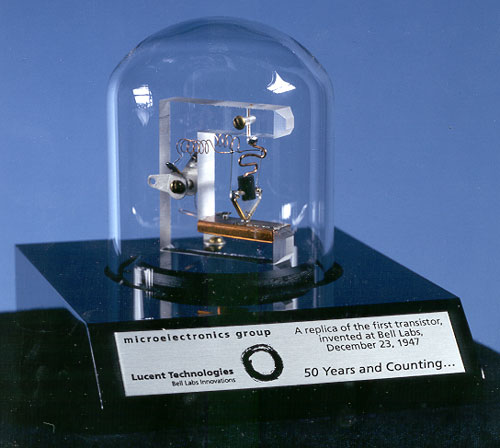
In the world of audio electronics, few components evoke as much mystique and debate as the germanium transistor. Born in the pioneering days of solid-state technology at Bell Labs in 1947, germanium was the material that powered the first generation of transistor radios, computers, and audio amplifiers. Though largely superseded by silicon since the 1960s due to silicon's superior thermal stability and consistency, germanium has refused to fade away. Instead, it has cultivated a legendary status, particularly among audio purists and guitarists, for its supposedly "warmer" and more "musical" sound.

Replica of the first transistor
A replica of the first point-contact transistor, invented at Bell Labs in 1947, marking the dawn of the solid-state era

This blog post dives into a specific and rather uncommon piece of this history: the 3AD56B, a high-power Chinese germanium transistor. Unlike the low-power transistors found in vintage fuzz pedals, the 3AD56B is a workhorse capable of driving speakers. We'll explore its characteristics, compare it to its silicon counterparts, and outline the design considerations for building a unique audio power amplifier that channels the spirit of the germanium era.

Understanding the 3AD56B: A Closer Look

The 3AD56B is a PNP germanium power transistor that stands out in a field dominated by low-power signal devices. While documentation can be sparse, data from DIY electronics forums and datasheets provides a solid picture of its capabilities. It was designed for audio frequency power amplification, making it an ideal candidate for a retro-style hi-fi or instrument amplifier project.

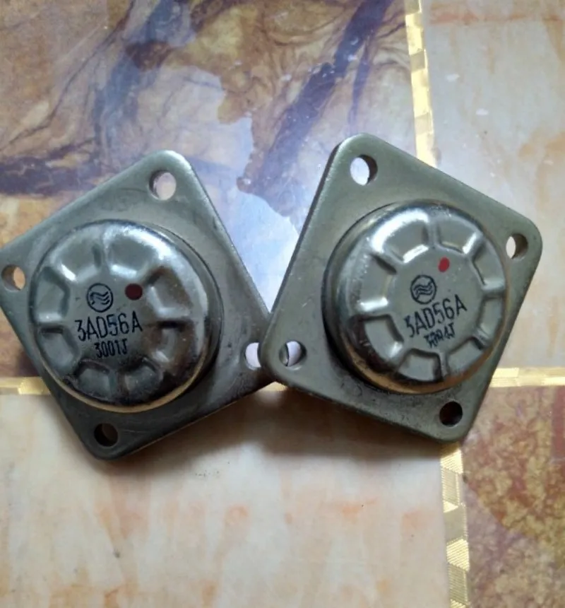
3AD56A Germanium Transistors
The 3AD56 series of high-power germanium transistors, ready for an audio amplifier project

Here are its key specifications, compiled from various sources:

Parameter Value Source
Type PNP Germanium DIYstompboxes.com
Max Power Dissipation (Pc) 50 W DIYstompboxes.com
Max Collector Current (Ic) 15 A Scribd Datasheet
Max Collector-Emitter Voltage (Vce) 45 V DIYstompboxes.com
DC Current Gain (hFE) 20 ~ 140 Scribd Datasheet
Transition Frequency (Ft) ≥ 3 KHz DIYstompboxes.com

These numbers reveal a transistor with significant power handling but a low frequency response, typical for early power germanium devices. The wide range of hFE (gain) is also characteristic, highlighting the manufacturing inconsistencies of the era and underscoring the importance of testing and matching components for any serious build.

Germanium vs. Silicon: Why Choose Germanium for an Amplifier?

The decision to use germanium over silicon is rarely about achieving technical perfection. Modern silicon transistors outperform germanium in almost every measurable way: they are more stable, more efficient, have higher gain, and are far cheaper. The choice, therefore, is about sonic character.

The Sonic Signature: Warmth and Organic Clipping

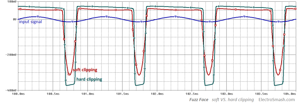
The "magic" of germanium is often attributed to its imperfections. When a transistor amplifier is pushed into distortion (clipping), the way it behaves defines its sound. Germanium has a lower forward voltage drop (around 0.3V) compared to silicon (around 0.7V), meaning it begins to clip earlier and more gradually. This creates what many describe as a "softer," "smoother," and more "organic" distortion, often compared to the natural breakup of a vacuum tube.

"Overall, when people are describing germanium transistor clipping, they often use the term 'organic.' Germanium transistor clipping, at least to me, often sounds tighter and less crunchy. All in all, it’s more akin to the natural breakup of a vacuum tube." - Crazy Chicken Guitar Pedals
Waveform showing soft vs hard clipping
A waveform comparison showing how soft clipping (red) gently rounds the signal peaks, typical of germanium, versus the sharper hard clipping (green) of silicon. Image courtesy of ElectroSmash

In contrast, silicon's sharper clipping "knee" results in a more aggressive, "harsher" distortion with more high-frequency harmonics. While this is desirable for modern high-gain sounds, the smoother onset of germanium distortion is what gives it the "vintage" warmth that builders of audio amplifiers often seek.

The Technical Trade-offs: Heat, Leakage, and Inconsistency

Working with germanium is not without its challenges. The two most significant are temperature sensitivity and leakage current.

  • Temperature Sensitivity: Germanium transistors are notoriously sensitive to heat. As they warm up, their characteristics change, which can lead to a dangerous feedback loop called "thermal runaway" where increasing temperature causes more current to flow, which in turn generates more heat. This makes proper heatsinking and bias circuit design absolutely critical.
  • Leakage Current: Compared to silicon, germanium transistors "leak" a significant amount of current even when they are supposed to be "off." This leakage is also temperature-dependent and must be accounted for in the circuit design, particularly in the biasing network.

These "flaws" are precisely why the electronics industry moved to silicon. However, for the DIY enthusiast, overcoming these challenges is part of the appeal, leading to a final product with a unique and tangible character.

Designing the Amplifier: Circuit Topologies for the 3AD56B

Building a power amplifier with the 3AD56B requires a thoughtful approach to circuit design. Given its characteristics, simply dropping it into a modern silicon-based schematic won't work. We must look to classic designs or clever hybrid solutions.

The Push-Pull Approach

For any power amplifier, a push-pull output stage is the standard. In this configuration, one transistor (or set of transistors) handles the positive half of the audio waveform, while another handles the negative half. This dramatically increases efficiency and power output compared to a single-ended (Class A) design and helps cancel out even-order harmonic distortion.

Quasi-Complementary OCL: The Classic Germanium Solution

The biggest challenge in the germanium era was creating matched pairs of complementary (PNP and NPN) power transistors. It was far easier to produce high-power transistors of a single polarity. This led to the development of the quasi-complementary circuit.

This clever design uses two identical polarity power transistors (like two 3AD56B PNPs) for the output stage, driven by a lower-power complementary pair of driver transistors. Online sellers of 3AD56B-based amplifier kits often mention using a "non-complementary same-polarity symmetrical OCL circuit," which is a direct reference to this topology (as seen on AliExpress). This is arguably the most "authentic" way to build a power amp with these devices.

A Hybrid Alternative: Modern Drivers for a Vintage Core

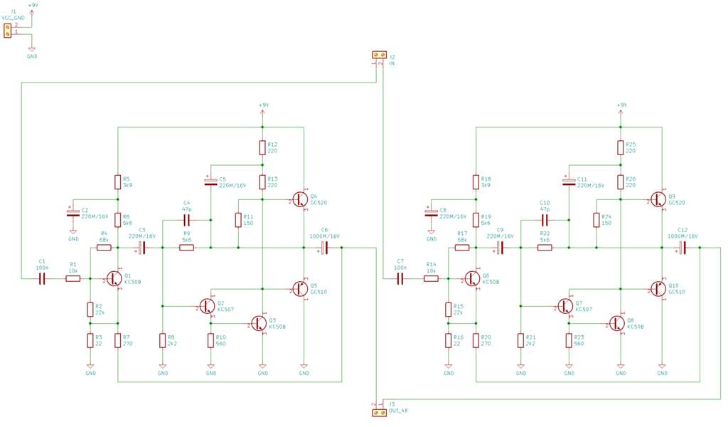
A more practical and stable approach is to build a hybrid amplifier. This design uses modern, reliable silicon transistors for the input and driver stages, taking advantage of their stability and high gain, while reserving the germanium 3AD56B transistors for the final output stage where their sonic character can shine through. This gives you the best of both worlds: the reliable performance of silicon and the vintage tone of germanium.

Some DIY builders have successfully adapted well-known silicon amplifier schematics by modifying the output stage for high-power germanium transistors, often using silicon drivers like the BD139/BD140 pair to provide a strong signal to the germanium finals (diyAudio Forum Discussion).

Schematic of a hybrid Germanium/Silicon amplifier
An example of a hybrid amplifier schematic, using silicon transistors for the input/driver stages and germanium transistors for the output. Source: MekWeb

Key Build Considerations: Taming the Germanium Beast

Regardless of the chosen topology, a successful build hinges on addressing germanium's inherent quirks.

Heatsinking is Non-Negotiable

The 3AD56B is rated for 50W of power dissipation. This power is converted almost entirely into heat. Without adequate heatsinking, the transistor will quickly overheat and destroy itself. A large, finned aluminum heatsink is essential for each output transistor to dissipate this heat and maintain a safe operating temperature, preventing thermal runaway.

Biasing for Stability and Sound

Biasing sets the idle (quiescent) current for the output transistors. Too little current causes "crossover distortion," a harsh sound that occurs as the signal crosses from the positive to the negative transistor. Too much current causes the transistors to run hot, waste power, and risk thermal runaway. The challenge with germanium is that the ideal bias point shifts with temperature. A classic solution is to use a germanium diode as part of the bias network, physically mounted on the same heatsink as the output transistors. As the transistors heat up, the diode heats up too, and its voltage drop changes in a way that counteracts the transistor's tendency to draw more current, thus stabilizing the bias (Vintage Radio Forum).

Component Selection and Matching

As noted, germanium transistors from the same batch can have widely varying gain (hFE). For a push-pull stage to work symmetrically and minimize distortion, it's crucial that the output transistors are a matched pair. This means buying more transistors than you need and using a multimeter with a transistor testing function (or a dedicated component tester) to find two with hFE values as close as possible.

Conclusion: Is It Worth the Hype?

Building an amplifier with the 3AD56B germanium transistor is not a project for the faint of heart, nor is it a path to achieving sterile, high-fidelity perfection. It is a journey into the heart of vintage audio technology, with all its challenges and charms. The process demands patience, careful component selection, and a solid understanding of the principles needed to tame these temperature-sensitive devices.

The reward is not found on a spec sheet. It's found in the unique sonic character—the smooth clipping, the organic warmth, and the satisfaction of creating a piece of audio equipment that sounds distinct from anything built with modern components. For the DIY audio enthusiast looking for a project that is both a technical challenge and a nostalgic exploration, breathing life into the 3AD56B is an adventure well worth taking. It's less about hype and more about heritage.

Thursday, August 7, 2025

Building Audio Amplifiers with Germanium Transistors: A Journey into Vintage Electronics

Building Audio Amplifiers with Germanium Transistors: A Journey into Vintage Electronics

Published by IWISTAO

When most electronics enthusiasts think about building amplifiers today, silicon transistors and integrated circuits dominate the conversation. However, there's something uniquely satisfying about working with germanium transistors – the workhorses of early semiconductor technology that helped launch the transistor revolution in the 1950s and 1960s. In this comprehensive guide, we'll explore how to design and build an audio amplifier using these fascinating vintage components.

Understanding Germanium Transistors

What Makes Germanium Special?

Germanium transistors were the first commercially viable bipolar junction transistors (BJTs), preceding their silicon counterparts by several years. These devices exhibit several distinctive characteristics that set them apart from modern silicon transistors:

Key Characteristics:

  • Lower forward voltage drop: Germanium diodes typically have a forward voltage of about 0.2-0.3V compared to silicon's 0.7V
  • Higher leakage current: Germanium transistors exhibit significantly higher collector-base leakage current (ICBO)
  • Temperature sensitivity: More susceptible to thermal runaway than silicon devices
  • Lower maximum operating temperature: Typically limited to around 85°C compared to silicon's 150°C+
  • Unique sonic character: Many audiophiles claim germanium devices impart a "warmer" sound

Common Germanium Transistor Types

For audio applications, several germanium transistor types remain popular:

  • 2N404/2N404A: PNP general-purpose transistors, excellent for audio
  • OC71/OC72: European PNP transistors, widely used in vintage designs
  • 2N1307: PNP medium-power transistor suitable for output stages
  • AC128: PNP transistor popular in European audio circuits

Historical Context and Modern Relevance

The Golden Age of Germanium

From 1947 to the mid-1960s, germanium ruled the semiconductor world. Bell Labs' first transistor was made from germanium, and virtually all early transistor radios, amplifiers, and electronic devices relied on these components. Companies like Philips, Mullard, and RCA produced millions of germanium transistors that powered everything from hearing aids to early computers.

Why Germanium Still Matters Today

Despite being largely superseded by silicon technology, germanium transistors maintain relevance for several reasons:

  1. Historical reproduction: Restoring vintage equipment requires period-correct components
  2. Unique audio characteristics: Many guitarists and audiophiles prefer the sound of germanium-based circuits
  3. Educational value: Understanding germanium devices provides insight into semiconductor physics and early circuit design
  4. Specialty applications: Some modern designs specifically exploit germanium's unique properties

Basic Amplifier Design Principles

Single-Stage Common Emitter Amplifier

The foundation of most germanium amplifier designs is the common emitter configuration, which provides both voltage and current gain. Let's examine the basic topology:

VCC (+9V)
 |
 R1 (10kΩ)
 |
 +---- OUTPUT
 |
 C   
B|---E  Q1 (2N404A)
 |
 R2 (1kΩ)
 |
 GND

Biasing Considerations for Germanium

Proper biasing is crucial for germanium transistors due to their high leakage current and temperature sensitivity. The collector-base leakage current (ICBO) can be 10-100 times higher than equivalent silicon devices, significantly affecting bias stability.

Critical biasing factors:

  • Use voltage divider biasing with low-impedance bias networks
  • Account for ICBO in bias calculations
  • Consider temperature compensation techniques
  • Implement DC coupling carefully due to voltage offset variations

Step-by-Step Amplifier Construction

Project: Single-Stage Audio Amplifier

Let's build a practical single-stage audio amplifier using a 2N404A germanium PNP transistor.

Circuit Design

Our amplifier will feature:

  • Input impedance: ~2kΩ
  • Voltage gain: ~20dB
  • Output impedance: ~500Ω
  • Frequency response: 50Hz - 15kHz

Schematic Analysis

INPUT ----C1----+
               |
               R1
               |
VCC-----------R2----+----C3----OUTPUT
 |                  |
 |           Q1(2N404A)
 |               |
 +----R3---------+
 |               |
 C2              R4
 |               |
GND-----------GND

Component Values:

  • C1: 10µF (input coupling)
  • C2: 100µF (power supply decoupling)
  • C3: 22µF (output coupling)
  • R1: 47kΩ (base bias)
  • R2: 10kΩ (collector load)
  • R3: 22kΩ (bias stability)
  • R4: 2.2kΩ (emitter resistor)
  • Q1: 2N404A (germanium PNP)

Construction Steps

Step 1: Prepare the Circuit Board

Start with a small piece of perfboard or stripboard. The compact layout is important for minimizing noise and parasitic capacitance.

Step 2: Install the Transistor

Mount the 2N404A transistor first, paying careful attention to pinout. For TO-1 metal can packages:

  • Case connects to collector
  • The tab indicates emitter
  • Base is the remaining pin

Step 3: Add Resistors

Install resistors in order of increasing value to avoid confusion. Use 1% metal film resistors for best performance and stability.

Step 4: Install Capacitors

Use high-quality capacitors:

  • Tantalum or aluminum electrolytic for C1 and C3
  • Low-ESR electrolytic for C2

Step 5: Wiring and Connections

Keep wire lengths short to minimize noise pickup. Use shielded cable for input connections if needed.

Component Selection and Considerations

Choosing Germanium Transistors

When selecting germanium transistors for audio applications, consider these factors:

Gain (hFE): Look for devices with hFE between 50-150. Higher gain transistors may be more prone to oscillation.

Leakage Current: Measure ICBO at room temperature. Values above 50µA may cause bias stability issues.

Matching: For differential pairs or push-pull configurations, match transistors for hFE and ICBO within 10%.

Supporting Components

Resistors: Use 1% tolerance metal film resistors for critical bias components. Carbon composition resistors can add vintage character but may introduce noise.

Capacitors:

  • Input/output coupling: Use film capacitors (polyester or polypropylene) for best audio performance
  • Power supply decoupling: Low-ESR aluminum electrolytic capacitors

Power Supply: Clean, well-regulated DC supply. Germanium circuits are more sensitive to supply noise than silicon equivalents.

Circuit Analysis and Calculations

DC Analysis

For our example circuit, let's calculate the operating point:

Assumptions:

  • VCC = 9V
  • hFE = 80 (typical for 2N404A)
  • ICBO = 10µA
  • VBE = 0.2V (germanium)

Base voltage calculation:
VB = VCC × R3/(R1 + R3) = 9V × 22kΩ/(47kΩ + 22kΩ) = 2.87V

Emitter voltage:
VE = VB - VBE = 2.87V - 0.2V = 2.67V

Emitter current:
IE = VE/R4 = 2.67V/2.2kΩ = 1.21mA

Collector current:
IC ≈ IE = 1.21mA

Collector voltage:
VC = VCC - (IC × R2) = 9V - (1.21mA × 10kΩ) = -3.1V

AC Analysis

Input impedance:
Zin = R1 || R3 || (hFE × R4) = 47kΩ || 22kΩ || (80 × 2.2kΩ) ≈ 2.1kΩ

Voltage gain:
Av = -R2/R4 = -10kΩ/2.2kΩ ≈ -4.5 (13dB)

Output impedance:
Zout ≈ R2 = 10kΩ

Construction Tips and Best Practices

Layout Considerations

  1. Ground plane: Use a solid ground plane or star grounding to minimize noise
  2. Component placement: Keep the transistor away from heat sources
  3. Lead dress: Route input and output leads away from each other to prevent feedback
  4. Shielding: Consider metal enclosure for RF immunity

Handling Germanium Transistors

Germanium transistors require special care:

  • Static sensitivity: While less ESD-sensitive than modern devices, use basic anti-static precautions
  • Thermal shock: Allow components to reach room temperature before handling
  • Lead forming: Make bends gradually to avoid crystal damage
  • Storage: Keep in anti-static foam or tubes

Soldering Techniques

  • Use low-temperature solder (60/40 rosin core)
  • Keep iron temperature below 300°C
  • Work quickly to minimize heat exposure
  • Use heat sinks on transistor leads when necessary

Testing and Troubleshooting

Initial Checkout

Before applying power, perform these checks:

  1. Visual inspection: Verify all connections and component orientations
  2. Continuity test: Check for short circuits, especially power supply rails
  3. Resistance measurements: Verify bias resistor values

Power-On Testing

With a current-limited power supply:

  1. Quiescent current: Should be 1-2mA for our example circuit
  2. DC voltages: Measure and compare to calculated values
  3. Signal injection: Apply small AC signal and verify amplification

Common Problems and Solutions

No output signal:

  • Check transistor pinout
  • Verify coupling capacitors aren't reversed
  • Measure DC bias voltages

Distorted output:

  • Bias point may be incorrect
  • Check for thermal runaway (rising collector current over time)
  • Verify input signal level isn't too high

Oscillation:

  • Add small capacitor (100pF) across collector-base
  • Check lead dress and layout
  • Reduce high-frequency gain if necessary

Thermal instability:

  • Improve heat sinking
  • Consider temperature compensation
  • Check for excessive ambient temperature

Performance Characteristics and Limitations

Frequency Response

Germanium transistors typically have lower transition frequency (fT) compared to modern silicon devices. Expect:

  • Useful audio bandwidth: DC to 20kHz
  • 3dB rolloff: Usually above audio range for single-stage designs
  • Phase response: Generally good for audio applications

Noise Characteristics

Germanium transistors exhibit higher noise than modern silicon devices:

  • Thermal noise: Similar to silicon at room temperature
  • Shot noise: Higher due to increased leakage current
  • 1/f noise: Can be significant at low frequencies

Temperature Stability

This remains the primary limitation:

  • Thermal runaway: More prone than silicon circuits
  • Bias drift: Significant over temperature range
  • Maximum operating temperature: Limited to ~85°C

Audio Performance

Despite technical limitations, many listeners prefer germanium amplifiers for:

  • Harmonic character: Predominantly even-order harmonics
  • Compression characteristics: Gradual clipping behavior
  • Frequency response: Often has pleasing high-frequency rolloff

Advanced Techniques

Temperature Compensation

For improved stability, consider these techniques:

Thermistor compensation:
Replace part of the emitter resistance with a negative temperature coefficient thermistor.

Diode compensation:
Use germanium diodes in the bias network to track VBE temperature variations.

Thermal coupling:
Mount compensation components in thermal contact with the transistor.

Push-Pull Output Stages

For higher power output:

VCC
 |
 R1
 |
INPUT----+----Q1 (PNP)----+----OUTPUT
         |                |
         +----Q2 (NPN)----+
         |                |
         R2               |
         |                |
        GND--------------GND

Use matched complementary pairs (2N404A PNP with 2N1306 NPN).

Feedback Techniques

Implement negative feedback for:

  • Improved linearity
  • Reduced distortion
  • Better frequency response
  • Enhanced stability

Maintenance and Long-term Reliability

Expected Lifespan

Well-designed germanium circuits can operate reliably for decades:

  • Avoid temperature extremes
  • Maintain clean, stable power supplies
  • Protect from humidity and contamination

Replacement Considerations

When germanium transistors fail:

  • Source quality NOS (New Old Stock) devices
  • Consider modern germanium reproductions
  • Match replacement devices carefully
  • Some silicon substitutes available but change circuit character

Conclusion

Building amplifiers with germanium transistors offers a unique glimpse into electronics history while producing circuits with distinctive sonic characteristics. While these devices present challenges – thermal instability, higher noise, and limited availability – they reward careful design and construction with a musical quality that many find appealing.

The key to successful germanium amplifier design lies in understanding and accommodating these transistors' unique properties rather than fighting them. Proper biasing, thermal management, and component selection are crucial for reliable operation.

Whether you're restoring vintage equipment, exploring audio circuit design, or simply seeking that elusive "vintage tone," germanium transistors provide an educational and rewarding platform for experimentation. The skills learned working with these temperamental devices – careful bias design, thermal analysis, and attention to construction detail – translate directly to more advanced analog circuit design.

As we've seen, germanium transistors may be vintage technology, but they still have much to teach us about the fundamentals of semiconductor devices and analog circuit design. In an age of digital processing and integrated circuits, there's something refreshingly hands-on about building an amplifier one discrete component at a time, especially when those components helped launch the semiconductor revolution nearly 75 years ago.

So fire up your soldering iron, dust off that vintage multimeter, and dive into the fascinating world of germanium electronics. Your ears – and your understanding of analog circuit design – will thank you.

Monday, July 14, 2025

A Guide to Power Amplifier Distortion and Mitigation Techniques

A Guide to Power Amplifier Distortion and Mitigation Techniques


 Published by IWISTAO

In the world of audio, achieving a pure, unaltered sound is the ultimate goal. However, as a signal passes through a power amplifier, it is susceptible to various forms of distortion. This article, based on detailed analysis of audio amplifier principles, explores the common types of distortion, their causes, and effective methods for their improvement. We will cover both classic analog distortions and modern digital solutions.

Distortion can be broadly categorized into two types: linear and non-linear. Linear distortion alters the amplitude and phase of different frequency components without adding new ones, while non-linear distortion introduces new frequency components, resulting in a harsh and unnatural sound. 


1. Harmonic Distortion (THD)

Harmonic Distortion is one of the most fundamental types of non-linear distortion, occurring when the amplifier's non-linear components create harmonics (multiples) of the original input frequency.

Characteristics

Total Harmonic Distortion (THD) is measured as the ratio of the sum of the powers of all harmonic components to the power of the fundamental frequency. A lower THD value indicates better performance. While a THD below 0.1% is generally imperceptible to the human ear, the character of the harmonics matters significantly.

  • Odd-order harmonics (3rd, 5th, etc.), common in solid-state ("stone") amplifiers, are often perceived as harsh and unpleasant.
  • Even-order harmonics (2nd, 4th, etc.), prevalent in tube ("valve") amplifiers, tend to sound more musical and warm, which is why some listeners prefer the "tube sound" even if the measured THD is higher.

It's crucial to note that THD specifications should always include measurement conditions (e.g., output power), as a low THD at 1W doesn't guarantee low distortion at higher power levels.


Mitigation Methods

  • Apply appropriate voltage or current negative feedback.
  • Use high-performance amplifying components with good linearity and high transition frequency (fT).
  • Ensure high consistency of matched pairs of transistors in circuit stages.
  • Employ Class-A amplification, known for its superior linearity.
  • Improve the power supply by increasing its power reserve and enhancing its filtering performance.


2. Intermodulation Distortion (IMD)

IMD occurs when two or more signals of different frequencies are amplified simultaneously, causing them to modulate each other and create new, non-harmonically related frequencies (sum and difference tones).

Characteristics

Unlike harmonic distortion, IMD products are not musically related to the original signal. This makes them easily detectable and particularly jarring to the human ear, often described as "harsh" or "piercing." IMD can reduce the clarity and sense of layering in the soundstage. For Hi-Fi amplifiers, an IMD of less than 0.1% is desirable.

Mitigation Methods

  • Use electronic crossover networks to limit the bandwidth of each amplifier channel or speaker driver.
  • Install a high-pass filter at the input to eliminate sub-low frequencies that can cause IMD.
  • Select components and circuit topologies known for good linearity.


3. Transient Distortion

Transient distortion relates to an amplifier's inability to accurately follow rapid, sudden changes in the input signal, such as the strike of a drum or a cymbal crash. It is a critical dynamic performance indicator.

A. Transient Intermodulation Distortion (TIM)

TIM, sometimes called "slew-induced distortion," was identified in the 1970s as a major culprit behind the harsh "transistor sound" of early solid-state amplifiers. 

Characteristics

It occurs in amplifiers with high levels of negative feedback. When a fast-rising signal is applied, the feedback loop cannot respond instantly due to propagation delays. For a moment, the amplifier operates in an open-loop state, causing the input stage to overload and clip. This momentary clipping generates a burst of high-frequency distortion.

Mitigation Methods

  • Limit the open-loop gain and the amount of negative feedback.
  • Use high-speed transistors (high fT) to reduce propagation delays.
  • Cancel the main feedback loop and rely on local feedback within each stage.
  • Use a leading (phase-advance) compensation network instead of a lagging one.
  • Increase the static current of the input stage to improve its dynamic range.

B. Slew Rate Induced Distortion

Slew Rate (SR) measures the maximum rate of change of an amplifier's output voltage, typically expressed in volts per microsecond (V/μs). If the input signal changes faster than the amplifier's slew rate, the output cannot keep up, resulting in a distorted, triangular-shaped waveform instead of the intended sine wave.

Characteristics

An amplifier with a high slew rate offers better resolution, layering, and positioning, especially with dynamic music. However, an excessively high slew rate can lead to instability and oscillation.

Mitigation Methods

  • Employ ultra-high-speed, low-noise transistors in the amplifier's design.
  • Ensure the slew rate of the preamplifier stage does not exceed that of the power amplifier stage to prevent TIM.


4. Other Common Distortions

Crossover Distortion

This occurs in Class-B and Class-AB push-pull amplifiers. It';s a non-linearity that happens around the zero-crossing point where one transistor turns off and the other turns on. It is most noticeable at low volumes and generates high-order harmonics. The primary solution is to apply a small amount of bias current to the output transistors (moving into Class-AB operation) to ensure a smooth transition.

Clipping Distortion

Clipping happens when the amplifier is driven beyond its maximum output voltage or current capabilities. The peaks of the waveform are "clipped" off, creating a square-like wave. This not only sounds harsh but also generates a large amount of high-frequency energy that can damage tweeters.

AC Interface Distortion

This is caused by the back electromotive force (EMF) from the speaker's voice coil movement, which feeds back into the amplifier's output and can interfere with its operation. Mitigation methods include using a well-designed power supply, selecting speakers with a suitable impedance curve, and ensuring a proper damping factor.


5. Modern Linearization Techniques

While the classic techniques above are fundamental to good analog design, modern systems, especially in wireless communications, rely on advanced digital signal processing (DSP) to enhance linearity and efficiency.

Power Back-off

The simplest way to ensure linearity is to operate the amplifier well below its maximum power capability (saturation point). This is known as power back-off. While effective, it comes at a significant cost to power efficiency, as much of the energy is dissipated as heat. 


The trade-off between power efficiency and output power. Power back-off is required to maintain linearity, but it reduces efficiency.


Digital Predistortion (DPD)

DPD is a powerful technique that has become essential in modern RF systems like 5G and Wi-Fi. It works by intentionally distorting the input signal in a way that is the inverse of the amplifier';s distortion characteristic. When this pre-distorted signal passes through the amplifier, the amplifier's non-linearity cancels out the pre-distortion, resulting in a clean, linear output. 

DPD models, often based on mathematical frameworks like the Generalized Memory Polynomial (GMP), can correct for both non-linearities and memory effects (where the amplifier';s behavior depends on past signals). This allows the amplifier to be operated closer to its saturation point, achieving both high linearity and high efficiency. More advanced DPD systems even use deep learning and neural networks for more accurate modeling. 


Other Advanced Techniques

Several other linearization methods exist, each with its own trade-offs:

  • Feedforward: This technique samples the amplifier's output, subtracts the original input to isolate the distortion, and then injects an anti-phase version of this distortion signal back into the output to cancel it. It is very effective and stable but can be complex and costly.
  • Feedback: This involves wrapping a feedback loop around the amplifier to correct errors. While common in audio (as negative feedback), its bandwidth is often limited in high-frequency RF applications.

A comprehensive overview of these techniques can be found in academic papers and industry reviews. 


Reference

[1]
Distortion In Power Amplifiers - Douglas Self
http://douglas-self.com/ampins/dipa/dipa.htm
[2]
Nonlinear Distortion - an overview | ScienceDirect Topics
https://www.sciencedirect.com/topics/engineering/nonlinear-distortion
[3]
Synergistic Approaches for Mitigation of Harmonic Distortion in …
https://ijereee.com/article/1%20May%202025%20IJEREEE.pdf
[4]
Selecting Capacitors to Minimize Distortion in Audio Applications
https://www.ti.com/lit/pdf/slyt796
[5]
A review on harmonic elimination and mitigation techniques in power …
https://www.sciencedirect.com/science/article/pii/S0378779624004590
[6]
Maximize Linearity in Amplifiers: Techniques with Transistors
https://www.infotransistor.com/maximize-linearity-in-amplifiers-techniques-with-transistors/
[7]
How to Improve Power Amplifier Linearity | Keysight
https://www.keysight.com/us/en/use-cases/improve-power-amplifier-linearity.html
[8]
Intermodulation Distortion in Active and Passive …
https://research.chalmers.se/publication/536155/file/536155_Fulltext.pdf
[9]
Optimization Techniques for Critical Issues in Power …
https://link.springer.com/content/pdf/10.1007/978-981-96-3216-9_3
[10]
Linear Distortion - an overview | ScienceDirect Topics
https://www.sciencedirect.com/topics/engineering/linear-distortion
[11]
[14]
Linearization as a Solution for Power Amplifier …
https://www.mdpi.com/2079-9292/10/9/1073
[15]
Enhancing Power Amplifier Linearity Via Hybrid Power Back …
https://ieeexplore.ieee.org/document/11035054
[16]
AES Journal Forum » Distortion Correction in Audio Power Amplifiers
https://secure.aes.org/forum/pubs/journal/?elib=3935
[17]Power Amplifier Linearization Techniques: An Overview