Showing posts with label IWISTAO. Show all posts

Friday, October 10, 2025

The Enduring Legend of the TDA1514A: Why This 90s Hi-Fi Chip Still Rocks

The Enduring Legend of the TDA1514A: Why This 90s Hi-Fi Chip Still Rocks

Published by IWISTAO

Contents

  • A Gem from the Golden Age of Hi-Fi
  • A Look Under the Hood: Power Meets Protection
    • Clean Power, Seriously Delivered
    • Built-in Intelligence: More Than Just Muscle
  • The Sound Signature: Why Audiophiles Still Listen
  • The DIY Dream: Building Your Own Legend
  • Still Relevant in 2025? Absolutely.
  • A Timeless Classic in a Silicon Package

In the world of audio, some components fade into obscurity while others become legends. They are whispered about in forums, sought after on auction sites, and revered by those who build their own sound systems. The Philips TDA1514A is one such legend. Born in the early 90s, this unassuming integrated circuit (IC) has outlasted countless trends, earning a permanent place in the hearts of hi-fi enthusiasts. But what makes a piece of silicon from over three decades ago still so compelling today?


A Gem from the Golden Age of Hi-Fi

To understand the TDA1514A, you have to travel back to its birth in 1992. Philips Semiconductors (now NXP Semiconductors) released this chip as the Compact Disc was cementing its reign. Digital audio demanded amplifiers that were not just powerful, but clean, detailed, and musical. The TDA1514A was engineered to be exactly that: a high-performance building block for a new generation of audio equipment . It wasn't just another chip; it was a statement of intent, rumored to have been designed with input from Marantz's chief audio engineer, a detail that gives it serious audiophile credibility .


A Look Under the Hood: Power Meets Protection

The TDA1514A';s spec sheet reads like a wish list for an audio designer of any era. It’s a mono amplifier, meaning you need two for a stereo setup, but this separation is often preferred for better channel isolation. It was designed to be robust, reliable, and, most importantly, to sound fantastic.


Clean Power, Seriously Delivered

The "50W" in its description isn't just a marketing number. The datasheet specifies it can deliver a solid 40 watts into an 8-ohm speaker or 48 watts into a 4-ohm load with exceptionally low distortion . This means it has the headroom to handle dynamic musical passages without breaking a sweat, rendering everything from a delicate cymbal tap to a powerful bass line with clarity and control. Its low Total Harmonic Distortion (THD) and Intermodulation Distortion ensure that the sound you hear is pure and uncolored—just the music, as it was intended.


Built-in Intelligence: More Than Just Muscle

What truly set the TDA1514A apart was its comprehensive suite of protection features. It includes thermal protection to prevent overheating and, crucially, Safe Operating Area (SOAR) protection. This sophisticated circuit actively monitors the output transistors, keeping them within safe voltage and current limits. The result is a nearly indestructible amplifier that can forgive the occasional short circuit or demanding load. It also features a mute/stand-by function to eliminate annoying pops and clicks during power-up or power-down, a touch of elegance that speaks to its thoughtful design.


The Sound Signature: Why Audiophiles Still Listen

Specs only tell half the story. The real magic of the TDA1514A is its sound. While often compared to other classics like the LM1875, the TDA1514A has a character all its own. Many describe its sound as warm, detailed, and effortlessly musical. It has a reputation for a strong and articulate mid-bass, a smooth midrange that brings vocals to life, and a high end that is clear without being harsh . It doesn't just amplify a signal; it imbues it with a sense of life and energy that is deeply engaging.


The DIY Dream: Building Your Own Legend

Perhaps the greatest testament to the TDA1514A';s legacy is its enduring popularity in the DIY audio community. Decades after its release, builders are still creating stunning amplifiers based on this chip. A quick search reveals countless schematics, project logs, and even ready-to-order PCBs on platforms like PCBWay . Its straightforward implementation and forgiving nature make it an excellent project for both seasoned builders and those new to the hobby. The satisfaction of powering on a self-built amplifier and hearing that legendary sound is an experience that never gets old.


Still Relevant in 2025? Absolutely.

In an age of hyper-efficient Class-D amplifiers, one might ask if a classic Class-AB chip like the TDA1514A is still relevant. The answer is a resounding yes. While modern chips from companies like Infineon or Texas Instruments offer incredible power efficiency in tiny packages, they often chase a different sonic goal. The TDA1514A isn't about efficiency; it's about a specific flavor of high-fidelity sound. It represents an era when circuit design was as much an art as a science. For those who prioritize musicality and the satisfaction of a classic design, the TDA1514A remains not just relevant, but highly desirable.


A Timeless Classic in a Silicon Package

The Philips TDA1514A is more than just an integrated circuit. It's a piece of audio history, a benchmark for performance, and a gateway into the rewarding world of DIY audio. It reminds us that great engineering and a focus on sound quality can create something truly timeless. So if you ever get the chance to listen to an amplifier built around this chip, do it. You might just understand why this 90s legend continues to rock the hi-fi world.


Reference

[1]
50W Audio Amplifier with TDA1514A | Electronic …
https://electronicscheme.net/50w-audio-amplifier-with-tda1514a/
[2]
TDA1514A DIY Guide - 50W High Performance Hi-Fi …
https://electro-dan.co.uk/electronics/tda1514.aspx
[3]
50 W high performance hi-fi amplifier - HandsOn Tec
https://www.handsontec.com/pdf_files/TDA1514A.pdf
[4]
TDA1514A datasheet(6/10 Pages) PHILIPS
[5]
[6]

Wednesday, October 1, 2025

From Clicks to Crescendos: Your Ultimate Guide to Hi-Fi Streaming

From Clicks to Crescendos: Your Ultimate Guide to Hi-Fi Streaming

Published by IWISTAO


The Old Ritual vs. The New Reality

Remember the ritual? The satisfying crackle of a needle dropping onto vinyl, the whir of a CD tray closing. For decades, high-fidelity audio was a tangible experience, a physical connection to the music. But in an age where entire music libraries live in the cloud, can the effortless convenience of streaming coexist with the purist's quest for perfect sound? The answer is a resounding yes, and it's more accessible and glorious than you might think.

The term Hi-Fi, short for High Fidelity, has always been about one thing: reproducing sound as accurately as possible to the original recording . For years, streaming was the antithesis of this philosophy. Born from a need for convenience, early services relied on heavy compression (think MP3s) that sacrificed sonic detail for smaller file sizes. For audiophiles, this was a non-starter. But the digital tide has turned.


The Rise of High-Resolution Audio Streaming

The streaming landscape of today is a world away from its humble beginnings. The new battleground isn't just library size; it's audio quality. Services like Tidal, Qobuz, Apple Music, and Amazon Music HD now champion "lossless" and ";hi-res" audio, terms that should be music to any audiophile';s ears. Lossless audio delivers CD-quality sound (typically 16-bit/44.1kHz), meaning no data is lost in compression. Hi-res audio goes even further, offering streams at 24-bit/96kHz or even 24-bit/192kHz, which can surpass the quality of the original CD master . Even Spotify, long the holdout, has finally embraced lossless streaming, cementing high-quality audio in the mainstream .


Bridging the Gap: Connecting Streaming to Your Hi-Fi System

So, you have a subscription to a hi-res service. How do you get that pristine digital signal to your beloved amplifier and speakers? You have several excellent options, each with its own balance of performance, convenience, and cost.


The Dedicated Network Streamer: The Purist's Choice

Think of a network streamer (or network audio player) as the modern equivalent of a high-end CD player. It';s a dedicated component designed to do one job exceptionally well: pull digital music from your home network or the internet and deliver it to your amplifier in the best possible quality. These devices often contain high-quality Digital-to-Analog Converters (DACs) and are built with audio performance as the top priority, making them the go-to choice for serious listeners .


The Streaming Amplifier: The Elegant Integrator

If you value a minimalist setup, a streaming amplifier is a fantastic solution. This single component combines a traditional integrated amplifier with a built-in network streamer. It dramatically reduces the number of boxes and cables in your system without a significant compromise in quality. Brands like Cambridge Audio, NAD, and Bluesound offer compelling all-in-one units that serve as the powerful, intelligent heart of a modern Hi-Fi system .


The Smart Upgrade: External DACs & Bluetooth

Perhaps you're not ready for a whole new component. You can still dramatically improve your streaming experience. Connecting a laptop directly to your amp's analog inputs is a start, but the built-in sound card is rarely up to snuff. An external DAC takes the digital signal (from your computer via USB, for example) and performs the crucial conversion to analog with far greater precision, unlocking a new level of clarity and detail . And what about Bluetooth? While traditionally shunned by audiophiles for its heavy compression, modern codecs like aptX HD and LDAC have made wireless streaming surprisingly capable. It's the ultimate in convenience, and while it may not match a dedicated wired streamer for critical listening, the quality is better than ever .

"Integrating streaming services transforms your home theater into a personalized entertainment hub." - HomeTheaterReviewPro.com


Optimizing Your Setup for Peak Performance

Getting the hardware is only half the battle. To truly make your system sing, a few optimizations can make a world of difference. After all, every component in the chain matters.


Wired vs. Wi-Fi: The Stability Debate

While modern Wi-Fi is fast, it's also susceptible to interference and network congestion. For the most stable, dropout-free playback—especially with large hi-res files—a wired Ethernet connection is the undisputed champion. Many high-end audio manufacturers recommend a wired connection for this very reason, as it eliminates a significant variable and ensures the data arrives uninterrupted .


The Role of Software: Roon and Streaming Protocols

Your playback software and the protocol it uses matter. For the ultimate experience, many audiophiles turn to Roon. It's a sophisticated music management platform that combines your local files and streaming services (like Tidal and Qobuz) into a single, beautiful interface, and it's designed for bit-perfect playback . Beyond Roon, you';ll encounter protocols like Apple's AirPlay 2, Google Cast, and DLNA. Each has its pros and cons regarding resolution support and device compatibility, so it's worth understanding which one best suits your ecosystem .

This power amplifier is connected with an Apple music base ( Apple WIFI router A1392), and music source is from Apple music player then play streamline music through wireless connection. Or you may use the Apple music base to play Spotify, Tidal, and so on. This setup allows you to stream music to your hi-fi system, integrating it seamlessly with other audio sources for high-quality playback.


IWISTAO 2X30W HIFI Amplifier Stereo LM1875 Power Amp Desktop With Preamp OP Independent Rectifier


Don't Forget the Power

It's an often-overlooked element, but your system is only as good as the electricity feeding it. "Dirty" power from your wall outlet, polluted with radio frequency (RF) and electromagnetic interference (EMI) from other appliances, can introduce noise and harshness into your sound. A dedicated audiophile power conditioner can filter this noise, providing a cleaner, blacker background from which the music can emerge .


Conclusion: The New Golden Age of Audio

The debate is over. Streaming has earned its place at the heart of the modern Hi-Fi system. It offers a universe of music—from the latest releases to obscure classics—without forcing a compromise on the sound quality we cherish. By choosing the right service, selecting the right hardware for your needs, and taking the time to optimize your setup, you can transform your listening room from a space with speakers into a veritable concert hall, all at the tap of a screen. Welcome to the new golden age of audio.

Reference

[1]
Best music streamers 2025: top network audio players ... - What Hi-Fi?
https://www.whathifi.com/best-buys/streaming/best-music-streamers
[3]
[4]
Hi-res music streaming services compared: is Tidal, Qobuz, …
https://www.whathifi.com/advice/hi-res-music-streaming-services-compared
[5]
Streaming HiFi Over Bluetooth: Unlocking the Future of High-Quality Audio
https://softhandtech.com/can-you-stream-hifi-over-bluetooth/
[6]
Spotify HiFi Is FINALLY Here, but It's Still Not as …
https://www.headphonesty.com/2025/09/spotify-hifi-compared-tidal-apple-qobuz/
[8]
Ultimate Guide to Hi-Fi Setup – Nottingham HiFi
https://nottinghamhifi.co.uk/blogs/blog/ultimate-guide-to-hi-fi-setup
[9]
[10]
Getting Into Hi-Fi: The $5000 *or less* hi-fi system challenge!
https://jeffsplace.positive-feedback.com/getting-into-hi-fi-the-5000-hi-fi-system-challenge/
[11]
The Best Hi-Fi Systems for Every Budget (2025) - HIFI Trends
https://hifitrends.com/2025/02/11/the-best-hi-fi-systems-for-every-budget-2025/
[12]
The 9 Best DACs (Digital-to-Analog Converters) …
https://consordini.com/best-dacs/
[13]
Elevate Your Sound: A Comprehensive Guide to Adding Bluetooth …
https://softhandtech.com/how-do-i-add-bluetooth-to-my-hifi/
[14]
8 Audiophile Source Components You Cannot …
https://www.moon-audio.com/blogs/expert-advice/best-audio-sources
[15]
MQA audio: what is it? And should you care? - What Hi-Fi?
https://www.whathifi.com/advice/mqa-audio-what-it-how-can-you-get-it
[17]
Top 5 High-End Network Players – Spring 2025 Rating
https://www.hifiverse.io/articles/audio/top-5-high-end-network-players
[18]
Best hi-fi systems 2025: CD, vinyl and streaming music players for the ...
https://www.whathifi.com/best-buys/all-in-one-systems/best-hi-fi-systems
[19]
Ethernet or WiFi – which is better for high-end audio streaming?
https://darko.audio/2018/08/ethernet-or-wifi-which-is-better-for-high-end-audio-streaming/
[23]
TIDAL Dumps MQA Right After Lenbrook Announces a New …
https://www.headphonesty.com/2024/06/tidal-officially-dumps-mqa/

Sunday, September 28, 2025

Deep Bass in Small Spaces: A Bookshelf Transmission Line Project

Deep Bass in Small Spaces: A Bookshelf Transmission Line Project

Published by IWISTAO 

In the world of DIY audio, some pairings feel like destiny. The purity of a single full-range driver, free from the complexities of a crossover, is one such siren call. The other is the transmission line (TL) enclosure, an "acoustic labyrinth" promising bass that is deep, articulate, and devoid of the common boominess of ported boxes. But what happens when you try to merge these two ideals into a compact, bookshelf-friendly form factor? This is where the real magic—and the real challenge—begins. We're embarking on a journey to design a bookshelf TL speaker around a common full-range driver with a resonant frequency (Fs) of 55 Hz. It's a quest to defy physics and coax profound bass from a small space.

There is an example for a bookshelf transmission line speaker as below.


The Dream Team: Full-Range Drivers and Transmission Lines

For many audiophiles, the combination of a full-range driver in a transmission line enclosure is the pursuit of an ideal. A single driver handles the entire frequency spectrum, eliminating the phase shifts and sonic discontinuities that can be introduced by crossover networks. The result is often described as a remarkably coherent and life-like soundstage. The transmission line complements this by tackling the most significant challenge for any small driver: low-frequency reproduction. Instead of simply trapping or crudely venting the driver's rear sound wave, a TL guides it down a long, damped path. As one source puts it, the goal is to take this back wave, invert its phase, and use it to reinforce the front wave, extending the bass response cleanly and powerfully .

The 55 Hz Conundrum: Quarter-Wavelength vs. The Bookshelf

Here's where our 55 Hz driver throws down the gauntlet. The foundational principle of a classic transmission line is the "quarter-wavelength rule." To get the exiting back wave in phase with the front wave at the driver's resonant frequency, the line's length should be one-quarter of that frequency's wavelength. Let's do the math.

The speed of sound in air is approximately 344 meters per second. The wavelength (λ) for our 55 Hz target is 344 m/s ÷ 55 Hz, which equals about 6.25 meters. A quarter of that is roughly 1.56 meters (about 5.1 feet). Now, the problem is obvious: how do you fit a five-foot-long pipe inside a box that can reasonably be called a "bookshelf" speaker? The answer lies in clever acoustic engineering: folding the line intricately within the cabinet, like a maze, and the strategic use of damping material.

Taming the Labyrinth: The Art and Science of Damping

An empty, folded pipe would be an acoustic disaster, creating a series of unwanted resonances, or "pipe organ" effects, that would ruin the sound. This is where damping material—the "soul" of the design—comes in. Stuffing the line with materials like long-fibre wool, polyester batting (Poly-fil), or acoustic foam serves two critical purposes.

First, it acts as a low-pass filter, absorbing the upper-bass and midrange frequencies of the back wave. This ensures that only the very lowest frequencies, which are less affected by the damping, emerge from the line's terminus, preventing coloration and smearing of the stereo image.

Second, and crucially for our bookshelf design, the damping material effectively slows the speed of sound within the line. This acoustic trick means a physically shorter line can be tuned to a lower frequency. The exact amount and density of stuffing is a delicate balancing act; too little and you get resonances, too much and you choke the bass output entirely. This is why TL design has historically been a process of painstaking trial and error, as noted by many DIY builders on forums like diyAudio.

From Blueprint to Box: Practical Design Choices

With the core principles in mind, let's move from theory to the practicalities of the build.

The Heart of the Matter: Choosing the Right Driver

Our starting point is a driver with an Fs of 55 Hz. But other Thiele-Small (T/S) parameters are just as important. For transmission lines, drivers with a low total quality factor Qts), typically below 0.4 or 0.5, are often preferred as they have better internal damping and control. A driver like the Tang Band W5-2143, with an Fs of 55 Hz and a Qts of 0.38, is an excellent real-world candidate for this project . The driver must also have a rigid cone to handle the air load of the long line without deforming.

Shaping the Sound: Line Geometry and Tapering

The shape of the line itself is a key design variable. While a constant cross-section line is simplest, many modern designs employ a tapered line that narrows from the driver towards the port. This tapering can help to suppress higher-order harmonics and smooth the overall frequency response. The initial cross-sectional area of the line is typically chosen to be between one to three times the driver's cone area (Sd), providing a good starting point for simulations.

The Exit Strategy: The Port and MLTLs

In its purest form, the end of the transmission line is simply an open terminus. However, a popular and highly effective variation is the Mass-Loaded Transmission Line (MLTL). As described by resources like Neurochrome, an MLTL is essentially a quarter-wave enclosure that also incorporates a tuned port. This hybrid design blurs the line between a pure TL and a bass-reflex box, allowing the port to act as a resonator to further shape and extend the low-frequency output, offering another layer of tuning flexibility.

The Modern DIY Advantage: Simulation Before Sawdust

For decades, designing a successful TL was a dark art. Pioneers like Perry Marshall, who derived his own mathematical models in the 1990s out of frustration with the lack of tools, highlight the historical difficulty . Today, the landscape has been transformed by powerful and accessible software.

The work of pioneers like Martin J. King, whose MathCad worksheets became a foundational resource for the DIY community, demystified the process . More recently, software like SpicyTL, which runs on the free LTspice circuit simulator, has provided an even more modular and intuitive way to model complex TL geometries, including tapering and damping effects . These tools allow you to simulate the entire system—driver, enclosure, and stuffing—and predict the frequency response with remarkable accuracy, turning what was once guesswork into a repeatable engineering process.

Conclusion: A Sound That Breathes

Designing a bookshelf transmission line speaker around a 55 Hz full-range driver is an ambitious project, but it is far from impossible. It represents a fascinating intersection of acoustic theory, clever packaging, and artistic tuning. By leveraging modern simulation tools to navigate the complexities of line length, folding, and damping, today's DIY builder can overcome the physical constraints of a small enclosure.

The reward for this effort is not just a speaker, but an experience. It's the satisfaction of creating a compact system that delivers a low-frequency performance of remarkable depth, clarity, and texture—a sound that, as its most ardent fans would say, doesn't just rumble, but truly breathes.

Reference

[1]
Transmission Line Speaker Calculation | Perry …
https://www.perrymarshall.com/articles/industrial/transmission-line/
[2]
Design Mass-Loaded Transmission Line Speakers | Neurochrome
https://neurochrome.com/pages/designing-mltl-speakers
[4]
A Viscous Damping Model of a Transmission Line …
http://www.quarter-wave.com/Horns/TL_and_BLH_Physics.pdf
[5]
[8]
Tang Band W5-2143 - 5″ Full-range 8Ω - Loudspeaker …
https://loudspeakerdatabase.com/TangBand/W5-2143
[9]
Transmission Line Speaker – Build Plan - soundblab.net
https://soundblab.net/product/transmission-line-speaker-build-plan/
[10]
Transmission line speaker design – Acoustical labyrinth
https://audiojudgement.com/transmission-line-speaker-design/

Wednesday, September 10, 2025

A DIY Guide: Building a Power Transformer for an EL34B Push-Pull Tube Amplifier

A DIY Guide: Building a Power Transformer for an EL34B Push-Pull Tube Amplifier

A DIY Guide: Building a Power Transformer for an EL34B Push-Pull Tube Amplifier

  • Published by IWISTAO

    Introduction: The Unsung Hero of Your Tube Amp

    In the pantheon of high-fidelity audio components, the vacuum tube amplifier holds a place of reverence. Its warm, rich, and dynamic sound is often attributed to the glowing tubes and the meticulously crafted output transformers. Yet, hidden within the chassis, lies a component of equal, if not greater, importance: the power transformer. This component is the silent, steadfast heart of the amplifier, providing the lifeblood—the electrical energy—that every other part of the circuit depends on. Without a robust, well-designed power transformer, even the most exotic tubes and sophisticated circuits will fail to perform.

    This article provides a comprehensive, step-by-step guide for the advanced DIY audio enthusiast on the intricate process of designing, calculating, and constructing a power transformer from scratch. We will embark on a journey from theoretical principles to hands-on craftsmanship, culminating in a custom-built transformer tailored for a classic stereo EL34B push-pull amplifier. This is not a project for the faint of heart, but for those willing to invest the time and diligence, the rewards are immeasurable.

    The Role of the Power Transformer

    At its core, a transformer is a simple device that uses the principle of magnetic induction to transfer electrical energy from one circuit to another without a direct connection . In a tube amplifier, the power transformer's primary function is to take the standard AC mains voltage (e.g., 120V or 230V) and convert it into several different AC voltages required by the amplifier's circuitry. These typically include:

    • A High-Voltage (B+) Secondary: This winding provides a high AC voltage (e.g., 300-500V) which, after being rectified and filtered, becomes the high-voltage DC supply (B+) for the plates and screen grids of the vacuum tubes.
    • Low-Voltage Filament (Heater) Windings: Vacuum tubes require a low voltage (commonly 6.3V or 5V) to heat their cathodes, enabling electron emission. The power transformer provides one or more of these low-voltage, high-current windings.
    • A Rectifier Filament Winding: If a tube rectifier is used (as in our example), it will require its own specific filament voltage, separate from the other tubes.

    It is crucial to distinguish the power transformer from the output transformer. While both operate on similar principles, their roles are distinct. The power transformer works at a fixed line frequency (50/60Hz) and is concerned with power delivery. The output transformer, conversely, must handle the entire audio frequency spectrum (20Hz-20kHz) and is responsible for impedance matching between the high-impedance output tubes and the low-impedance speakers .

    Why Build Your Own?

    In an age of readily available commercial components, why undertake the complex task of building a power transformer? The motivations are compelling for the dedicated enthusiast:

    1. Uncompromising Customization: Commercial transformers are built to general specifications. Building your own allows you to create a transformer perfectly matched to the unique voltage and current demands of your specific amplifier design, optimizing performance and efficiency.
    2. Superior Quality: The DIY route grants you complete control over material selection. You can choose premium-grade silicon steel for the core, high-purity copper wire, and superior insulation materials, often exceeding the quality of off-the-shelf units, especially those in lower price brackets .
    3. The Pursuit of Knowledge: The process of designing and winding a transformer demystifies a critical component of audio electronics. It provides a profound understanding of electromagnetic principles and their practical application, a level of insight that cannot be gained from simply assembling a kit.
    4. The Ultimate Satisfaction: There is a unique and deep satisfaction in listening to an amplifier powered by a core component you have crafted with your own hands, from raw materials to a finished, functional work of art.

    However, this journey is not without its challenges. It demands patience, precision, and an unwavering commitment to safety. As one DIY audio forum member noted, transformer design is a "highly complex" field not recommended for complete novices .

    Prerequisites & Safety Warning

    Before proceeding, it is essential to acknowledge the gravity of this undertaking. This is an advanced project that assumes a solid foundation in electronics theory, proficiency with calculations, and practical skills in soldering and assembly.

    DANGER: HIGH VOLTAGE. A tube amplifier's power supply operates at voltages that are extremely dangerous and can be lethal. The voltages present in a power transformer, both during testing and in operation, can cause severe injury or death. All testing and handling must be performed with extreme caution, using appropriate safety equipment and procedures (such as a dim-bulb tester and a variac). If you are not completely confident in your knowledge of high-voltage safety protocols, **DO NOT ATTEMPT THIS PROJECT.** Your safety is paramount.

    Part 1: The Blueprint - Designing and Calculating Your Transformer

    The success of a DIY transformer hinges entirely on the meticulous work done before a single wire is wound. The design and calculation phase is the blueprint that dictates every subsequent step. A mistake here will, at best, result in a poorly performing transformer; at worst, it can lead to catastrophic failure and a significant safety hazard. In this section, we will use a concrete example to walk through the process: designing a power transformer for a stereo push-pull amplifier.

    The Goal: From Circuit Needs to Transformer Specs

    A power transformer is never designed in isolation. Its specifications are a direct reflection of the demands of the amplifier circuit it is intended to power . Therefore, the first step is always to define the amplifier's architecture.

    Our Example Project: A stereo, Class A/B push-pull amplifier.
    • Power Stage: 4 x EL34B vacuum tubes (two per channel).
    • Preamp/Driver Stage: 2 x 12AX7 vacuum tubes (one per channel, serving as input gain and phase splitter).
    • Rectification: 1 x 5U4G tube rectifier for the B+ supply.

    Our goal is to translate the power requirements of these components into a concrete set of specifications for our transformer's primary and secondary windings.

    Step 1: Determine Power Requirements (The "Why")

    We must calculate the voltage and current required by each part of the circuit. This involves consulting tube datasheets and understanding the operating conditions of the amplifier.

    High Voltage (B+) Winding

    This winding supplies the plate and screen grid voltages for all the tubes.

    1. Target DC Voltage (VDC): EL34B datasheets and common push-pull designs suggest a range of operating points. A popular and effective choice for a balance of power and tube longevity is a B+ voltage around 400V DC . However, for our example, let's choose a slightly more conservative target of 350V DC under load. This voltage will be delivered by a full-wave rectifier using a center-tapped secondary winding.
    2. Total DC Current Draw (IDC): We need to sum the quiescent (idle) current of all tubes connected to the B+ supply.
      • Power Tubes (EL34B): In a Class A/B push-pull configuration, a typical idle current per tube is around 70mA to achieve a plate dissipation of 25W at 350V . For four tubes, this is `4 x 70mA = 280mA`.
      • Preamp Tubes (12AX7): A 12AX7 in a typical preamp or phase splitter circuit draws a very small current, around 1.2mA to 2mA per triode section. Since each 12AX7 has two triodes, and we have two tubes, a safe estimate is `2 tubes * 2 sections/tube * 2mA/section = 8mA`.
      • Total DC Current: `280mA (EL34B) + 8mA (12AX7) = 288mA`. We'll round this up to 300mA for a small margin.
    3. Required AC RMS Current (IAC): This is a critical and often misunderstood calculation. For a power supply with a capacitor-input filter (the most common type), the transformer must deliver current in short, high-amplitude pulses to charge the capacitor. This means the RMS current in the secondary winding is significantly higher than the DC load current. A common rule of thumb is that the AC RMS current rating for a full-wave, center-tapped winding should be 1.5 to 1.8 times the DC current . Using a factor of 1.8 for a conservative design: `I_AC = 300mA * 1.8 = 540mA`.
    4. Required AC Voltage (VAC): For a full-wave tube rectifier (like the 5U4G) with a capacitor-input filter, the resulting DC voltage is roughly 1.1 to 1.2 times the AC RMS voltage of one half of the center-tapped secondary, minus the voltage drop across the rectifier tube. The 5U4G has a significant voltage drop, around 50V at this current. So, to get 350V DC, we need: `V_DC ≈ (V_AC * 1.1) - V_drop`. Rearranging: `V_AC ≈ (V_DC + V_drop) / 1.1 = (350V + 50V) / 1.1 ≈ 364V`. We'll round this to 370V AC. Therefore, our B+ winding will be 370V - 0 - 370V.

    Filament (Heater) Windings

    These low-voltage windings power the tube heaters. It's good practice to use separate windings for the power tubes and preamp tubes to prevent noise from the high-current power tube filaments from coupling into the sensitive preamp stages.

    • Power Tube Filament Winding:
      • EL34B Heater: `6.3V @ 1.5A` each .
      • Total for four tubes: `4 * 1.5A = 6.0A`.
      • Specification: 6.3V @ 6.0A. It's wise to add a 20% current margin, so we'll design for `~7.2A`.
    • Preamp Tube Filament Winding:
      • 12AX7 Heater: `6.3V @ 0.3A` each.
      • Total for two tubes: `2 * 0.3A = 0.6A`.
      • Specification: 6.3V @ 0.6A. With margin, we'll design for `~0.75A`.
    • Rectifier Filament Winding:
      • 5U4G Heater: Requires its own dedicated, insulated winding.
      • Specification: 5V @ 3A. With margin, we'll design for `~3.6A`.

    Calculate Total Power (VA Rating)

    The Volt-Ampere (VA) rating is the apparent power of the transformer. We calculate it by summing the VA of each secondary winding.

    • B+ Winding VA: `(370V + 370V) * 0.540A = 740V * 0.540A = 399.6 VA`. Note: We use the full winding voltage and the calculated AC RMS current.
    • Power Tube Filament VA: `6.3V * 7.2A = 45.36 VA`.
    • Preamp Tube Filament VA: `6.3V * 0.75A = 4.73 VA`.
    • Rectifier Filament VA: `5V * 3.6A = 18.0 VA`.

    Total Secondary VA: `399.6 + 45.36 + 4.73 + 18.0 = 467.69 VA`.

    Transformers are not 100% efficient. We must also account for core and copper losses, typically assuming an efficiency of around 90%. Furthermore, a safety margin is crucial to ensure the transformer runs cool and can handle inrush currents when first powered on. A 25-30% overall margin is a good engineering practice.

    Final Required VA Rating: `467.69 VA * 1.25 ≈ 585 VA`. We will design a transformer with a power rating of approximately 600 VA.

    Step 2: Select the Core and Bobbin (The "What")

    The core is the magnetic heart of the transformer. Its size and material dictate the transformer's power handling capacity and efficiency .

    Core Size vs. Power

    The power a transformer can handle is directly related to the cross-sectional area (A) of its core's center leg. A larger core can handle more magnetic flux before saturating, thus enabling higher power transfer. A widely used empirical formula for standard EI laminations at 50/60Hz is:

    A (in cm²) ≈ 1.15 * √P (in VA)

    For our 600 VA transformer:

    A ≈ 1.15 * √600 ≈ 1.15 * 24.5 ≈ 28.18 cm²

    We now need to find a standard EI lamination size that can provide this core area. The core area is the product of the center tongue width and the stack height of the laminations. For example, an EI-120 lamination has a tongue width of 4.0 cm. To get an area of ~28.2 cm², we would need a stack height of `28.2 / 4.0 = 7.05 cm`. So, an EI-120 core with a 70mm stack would be a suitable choice.

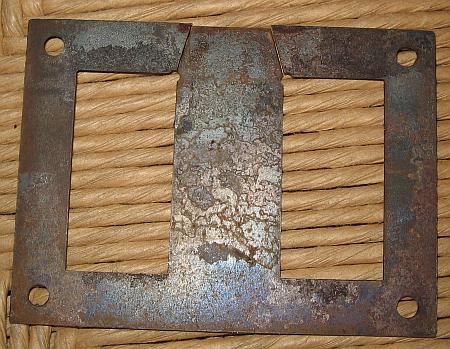
    E-I type transformer lamination
    A typical E-I lamination set, the fundamental building block of many power transformers. The alternating stack of these pieces forms the magnetic core

    Core Material and Type

    For audio applications, especially power transformers, the choice of core material is critical for minimizing losses and unwanted noise.

    • Material: High-quality, grain-oriented (or non-oriented) silicon steel is the standard. A common grade is M6, which has low core loss at 60Hz. The laminations should be thin, typically 0.35mm (0.014 inches), to minimize eddy current losses .
    • Type: While toroidal cores offer lower stray magnetic fields and higher efficiency, traditional EI laminations are more accessible for DIY builders, easier to wind on a bobbin, and embody the classic transformer construction method . We will proceed with an EI core design.

    Bobbin Selection

    The bobbin is the insulating form onto which the wires are wound. It must be chosen to match the core size (EI-120 in our case). Crucially, the bobbin's "window area" must be large enough to physically accommodate all the calculated windings, including the space taken up by insulation. A preliminary check can be done, but the final confirmation often comes after calculating the space each winding will occupy. It's always better to choose a bobbin with a slightly larger window than you think you need.

    Step 3: Calculate the Windings (The "How")

    Now we translate our voltage requirements into the physical number of turns of wire for each winding.

    Turns Per Volt (TPV)

    The fundamental transformer equation relates voltage, frequency, core area, flux density, and the number of turns:

    V = 4.44 * N * f * A * B

    Where: V = Voltage (Volts), N = Number of turns, f = Frequency (Hz), A = Core Area (m²), B = Max Flux Density (Tesla).

    We can rearrange this to find the Turns Per Volt (TPV = N/V). For DIY purposes, a simplified and conservative rule of thumb is often used, which implicitly assumes a safe flux density (B ≈ 1.0-1.2 Tesla) for standard silicon steel to avoid core saturation:

    TPV ≈ 45 / Core Area (in cm²)

    Using our calculated core area of 28.18 cm²:

    TPV ≈ 45 / 28.18 ≈ 1.6 Turns Per Volt

    Number of Turns for Each Winding

    Now we apply the TPV to our voltage specifications. It's vital to add a compensation factor (typically 5-10%) to the secondary windings to account for voltage drop (IR drop) under load. We'll use 5%.

    • Primary Winding (assuming 230V mains):
      • Turns = Mains Voltage * TPV = 230V * 1.6 T/V = 368 Turns
    • High-Voltage (B+) Secondary:
      • Turns (per half) = Target Voltage * TPV * 1.05 = 370V * 1.6 T/V * 1.05 = 621.6 Turns
      • We'll use 622 turns for each half. So, the winding will be 1244 turns total, with a tap at 622 turns.
    • Power Tube Filament Secondary:
      • Turns = 6.3V * 1.6 T/V * 1.05 = 10.58 Turns. We'll round up to 11 Turns.
    • Preamp Tube Filament Secondary:
      • Turns = 6.3V * 1.6 T/V * 1.05 = 10.58 Turns. We'll also use 11 Turns.
    • Rectifier Filament Secondary:
      • Turns = 5.0V * 1.6 T/V * 1.05 = 8.4 Turns. We'll use 9 Turns.

    Wire Gauge (AWG/SWG)

    The diameter of the wire for each winding is determined by the current it must carry. A wire that is too thin for its current will overheat, melt its insulation, and cause a short circuit. A common rule for transformer winding is to use a current density of 2.5 to 3.0 Amperes per square millimeter (A/mm²) of wire cross-section.

    We can consult a standard wire gauge table (AWG or SWG) that lists the diameter and cross-sectional area for each gauge number.

    1. Primary Winding: First, calculate the primary current: `I_primary = Total VA / V_primary = 600 VA / 230V = 2.61A`. Using a density of 2.5 A/mm², we need a wire area of `2.61A / 2.5 A/mm² = 1.044 mm²`. This corresponds to approximately 17 AWG wire.
    2. High-Voltage Secondary: The AC RMS current was calculated as 540mA (0.54A). Required area: `0.54A / 2.5 A/mm² = 0.216 mm²`. This corresponds to approximately 24 AWG wire.
    3. Power Tube Filament: Current is 7.2A. Required area: `7.2A / 2.5 A/mm² = 2.88 mm²`. This is a thick wire, corresponding to approximately 12 AWG.
    4. Preamp Tube Filament: Current is 0.75A. Required area: `0.75A / 2.5 A/mm² = 0.3 mm²`. This corresponds to approximately 22 AWG.
    5. Rectifier Filament: Current is 3.6A. Required area: `3.6A / 2.5 A/mm² = 1.44 mm²`. This corresponds to approximately 15 AWG.

    With these calculations complete, we have a full blueprint for our transformer. The next step is to bring it to life.

    Part 2: The Craft - Winding and Assembling the Transformer

    This section transitions from the abstract world of calculations to the tangible, hands-on process of construction. It is a craft that rewards patience, precision, and a methodical approach. The quality of the winding directly impacts the transformer's performance, reliability, and quietness of operation.

    Step 1: Preparation - Materials and Tools

    Gathering all necessary materials and tools before starting is essential for a smooth workflow. A well-organized workspace is a safe workspace.

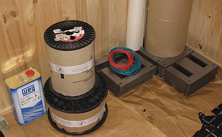
    Materials for transformer winding
    Essential materials for transformer construction: EI laminations, spools of enamelled wire, and insulating varnish

    Materials Checklist:

    • EI Laminations: EI-120, M6 grade, 0.35mm thickness, sufficient for a 70mm stack.
    • Bobbin: One EI-120 bobbin, made of phenolic, Ryton®, or another high-temperature plastic.
    • Enameled Copper Wire: The calculated gauges (12, 15, 17, 22, 24 AWG). Ensure you have enough length for each winding, plus extra.
    • Insulation Paper: Mylar or Nomex paper of various thicknesses. Typically 0.05mm for layer insulation and 0.25mm for inter-winding insulation.
    • Insulation Tape: High-temperature tape such as Kapton or fiberglass-reinforced tape.
    • Lead-out Wires: Flexible, high-temperature insulated wire (Teflon or silicone) of appropriate gauges to connect to the magnet wire ends.
    • Hardware: End bells (clamps) and bolts/nuts suitable for an EI-120 core.
    • Insulating Varnish: A can of air-drying or baking electrical insulating varnish.

    Tools Checklist:

    • Winding Machine: A manual hand-cranked or a slow-speed motorized coil winder with a turns counter is indispensable.
    • Soldering Iron & Solder: For connecting lead-out wires.
    • Wire Strippers/Scraper: To remove enamel from the magnet wire ends.
    • Multimeter: Essential for testing during and after construction.
    • Rubber Mallet: For tapping laminations into place.
    • Safety Gear: Safety glasses are a must.

    Step 2: Bobbin Preparation

    The bobbin provides the structural and insulating foundation for the windings. Proper preparation is key.

    1. Inspect: Carefully inspect the bobbin for any sharp edges or molding flash, especially on the inside corners where the wire will turn. Smooth any imperfections with a small file or sandpaper to prevent damage to the wire's delicate enamel insulation.
    2. Insulate the Core Tube: Wrap the central part of the bobbin (the core tube) with two to three layers of Kapton or Mylar tape. This provides an extra layer of insulation between the windings and the iron core that will eventually be inserted .

    Step 3: Primary Winding

    The primary winding is the first to be wound onto the bobbin. It must be done with the utmost care as it is the foundation for all other windings.

    1. Anchor the Start: Solder a flexible lead-out wire to the start of your primary magnet wire (17 AWG). Be sure to thoroughly scrape the enamel off the magnet wire first to ensure a solid connection. Insulate the solder joint with heat-shrink tubing. Securely anchor this lead-out wire to the bobbin's flange.
    2. Wind the First Layer: Begin winding, ensuring each turn lies flat and tight against the previous one. There should be no gaps or overlaps. This is called a "neat" or "perfect" layer. The tension should be firm but not so tight as to stretch the wire or deform the bobbin.
    3. Insulate Between Layers: Once the first layer is complete, cut a piece of 0.05mm insulation paper to the width of the bobbin window. Wrap one full layer of this paper over the winding, securing it with a small piece of tape. This layer insulation is critical to prevent voltage breakdown between layers .
    4. Continue Winding: Wind the subsequent layers, each in the opposite direction to the last. After every single layer, apply another sheet of insulation paper. Keep a precise count of the turns.
    5. Secure the End: Once you have wound the calculated 368 turns, secure the end of the wire, solder on its lead-out wire, and anchor it to the bobbin flange, ensuring it cannot unravel.

    Step 4: Inter-winding Insulation

    This is arguably the most critical safety step in the entire process. The insulation between the primary (mains voltage) and secondary windings must be robust enough to withstand high voltage potentials and prevent a catastrophic failure.

    Do not cut corners here. A failure of this insulation could connect lethal mains voltage directly to your amplifier's chassis and secondary circuits.

    Wrap at least three to five layers of thicker (e.g., 0.25mm) insulation paper over the entire completed primary winding. Follow this with two to three tightly-wrapped layers of fiberglass or Kapton tape. This creates a formidable dielectric barrier.

    Step 5: Secondary Windings

    The secondaries are wound on top of the insulated primary. A logical order is to wind the high-voltage winding first, followed by the lower-voltage filament windings.

    1. High-Voltage Winding:
      • Start the 24 AWG wire just as you did the primary.
      • Wind the first 622 turns, applying layer insulation after each layer.
      • At the 622nd turn, carefully pull a loop of wire out from the side of the bobbin. This will be your center tap. Secure it well so it doesn't get pulled back in, and protect it with tubing.
      • Continue winding the second 622 turns, maintaining the same winding direction on the bobbin.
      • Finish the winding and attach the final lead-out wire.
    2. More Insulation: After completing the high-voltage winding, apply another heavy layer of inter-winding insulation (3-4 layers of 0.25mm paper) to isolate it from the filament windings.
    3. Filament Windings:
      • These windings use much thicker wire and have very few turns (9-11 in our case). They can be tricky to wind neatly.
      • Wind the 5V rectifier winding first (15 AWG, 9 turns).
      • Apply a layer of insulation.
      • Wind the 6.3V power tube filament winding (12 AWG, 11 turns).
      • Apply a layer of insulation.
      • Wind the 6.3V preamp filament winding (22 AWG, 11 turns).
      • It is good practice to twist the lead-out wires for the filament windings together to help cancel out their magnetic fields and reduce induced hum.

    Step 6: Final Insulation and Core Assembly

    The winding process is complete. The final steps involve protecting the windings and assembling the iron core.

    1. Final Wrap: Wrap the entire finished bobbin with several layers of durable tape (like yellow transformer tape or fiberglass tape) to protect the outer windings from abrasion during core assembly.
    2. Insert Laminations: Begin inserting the EI laminations into the bobbin's core opening. For a power transformer, the core must be fully interleaved with no air gap. This is achieved by inserting the 'E' and 'I' pieces in an alternating pattern. Insert one 'E' from the left, then one 'I' from the right to fill the gap. Then, insert the next 'E' from the right, and its 'I' from the left. Continue this `1x1` alternating pattern .
    3. Stack Tightly: The laminations will be a tight fit. Use a rubber mallet to gently tap them into a tight, uniform stack. The goal is to fit as many laminations as possible to achieve the designed stack height (70mm).
    4. Clamp the Core: Once the core is fully stacked, place the end bells (clamps) over the ends of the stack and secure them with the bolts and nuts. Tighten the bolts firmly and evenly, but do not overtighten to the point where the laminations are bent or distorted, as this can increase core losses and audible hum.

    Step 7: Finishing (Optional but Recommended)

    Varnishing the completed transformer offers several benefits: it helps to mechanically secure the windings and laminations, significantly reducing audible hum or buzz; it improves thermal conductivity, helping heat dissipate from the core; and it protects the transformer from moisture and corrosion .

    The process, known as vacuum pressure impregnation (VPI) in industrial settings, can be approximated by the DIYer:

    1. Pre-heat: Gently warm the transformer in an oven to about 50-60°C to drive out any trapped moisture.
    2. Immerse: While still warm, fully submerge the transformer in a container of electrical insulating varnish. The warmth helps the varnish flow into the smallest crevices. If you have a vacuum chamber, placing the container inside and pulling a vacuum will remove all trapped air bubbles, ensuring complete penetration.
    3. Drip and Cure: After soaking for an hour or more, remove the transformer and hang it to allow excess varnish to drip off.
    4. Bake: Cure the transformer in an oven according to the varnish manufacturer's instructions. This typically involves several hours at a specific temperature (e.g., 8-12 hours at 100-120°C). This process will polymerize the varnish into a hard, solid block.

    The result is a mechanically solid, quiet, and professionally finished transformer, ready for the final and most important phase: testing.

    Part 3: The Verdict - Testing and Verification

    With the transformer fully assembled and cured, the moment of truth arrives. This final stage is not merely a formality; it is a critical safety and quality assurance process. Thorough testing verifies that the transformer has been built correctly, performs to its design specifications, and is safe to install in your amplifier.

    Safety First: The Cardinal Rule

    Before connecting any power, perform a series of "cold" checks with a multimeter. These checks can identify major faults like short circuits or open windings without any risk.

    Reiteration of Warning: All "hot" tests involving mains voltage must be conducted with extreme caution. Always use a dim-bulb tester or a variac (variable autotransformer) to slowly bring up the voltage for the initial power-on. This can prevent catastrophic damage in case of a short circuit. Work with one hand in your pocket to avoid creating a current path across your chest.

    Checklist for a Healthy Transformer

    Follow this sequence of tests methodically. Do not proceed to the next step if a test fails.

    1. Visual Inspection

    Carefully examine the entire transformer. Look for any nicks or scrapes in the wire insulation, loose lead-out wires, signs of arcing, or physical damage to the core or bobbin. Ensure all hardware is tight.

    2. Continuity and DC Resistance (DCR) Check (Cold Test)

    Use a multimeter in resistance (Ohms) mode.

    • Purpose: To verify that each winding is a continuous copper path and to get a baseline DCR reading.
    • Procedure: Measure the resistance between the two lead-out wires of each winding.
      • Primary: Should read a low resistance, typically 5-20 Ω for a transformer this size.
      • High-Voltage Secondary: This has many turns of fine wire, so its resistance will be higher, likely in the 80-150 Ω range from end-to-end. The resistance from each end to the center tap should be almost identical (within 1-2%).
      • Filament Windings: These are few turns of thick wire, so their resistance will be very low, often less than 1 Ω.
    • Expected Result: Each winding should show a stable, non-zero resistance. A reading of infinity (O.L.) indicates a broken wire (open circuit). A reading of zero indicates a dead short.

    3. Isolation Check (Cold Test)

    This is the most important safety check.

    • Purpose: To ensure there is no electrical connection between separate windings or between any winding and the iron core.
    • Procedure: Set your multimeter to its highest resistance range (MΩ). Measure the resistance between:
      1. The primary and the core.
      2. The secondary HV winding and the core.
      3. The primary and the secondary HV winding.
      4. The primary and each filament winding.
      5. The HV secondary and each filament winding.
    • Expected Result: All measurements must read infinite resistance (O.L. on a digital meter). Any measurable resistance, no matter how high, indicates a critical insulation failure. The transformer is unsafe and must not be powered on. A proper insulation tester (Megger) would show a resistance well above 500 MΩ at 500V.

    4. No-Load Test (Hot Test - Use Extreme Caution)

    This is the first time the transformer will see mains voltage.

    • Purpose: To verify the turns ratio is correct by measuring the output voltages and to check for excessive no-load current, which would indicate a shorted turn or core problem.
    • Procedure:
      1. Place the transformer on a non-conductive surface. Ensure no leads are touching.
      2. Connect the primary winding to your mains outlet **through a dim-bulb tester**. A 60W or 100W incandescent bulb is suitable.
      3. Power on. The bulb should flash brightly for an instant (as the core magnetizes) and then settle to a very dim glow. If the bulb stays bright, you have a short circuit. Immediately power off and investigate.
      4. If the bulb is dim, it is safe to proceed. Use your multimeter in AC Volts mode to carefully measure the voltage across each secondary winding.
      5. Measure the no-load primary current using a clamp meter or another multimeter in series (AC Amps mode). This is best done after removing the dim-bulb tester and using a variac to apply the exact rated voltage.
    • Expected Result:
      • Voltages: The measured secondary voltages will be slightly higher (typically 5-10%) than the design voltage because there is no load to cause a voltage drop. For our design: HV secondary might be ~780-810V end-to-end, filaments ~6.6-6.9V, etc.
      • No-Load Current: The primary current should be very low, typically less than 100mA for a well-made transformer of this size. High no-load current indicates a problem.

    5. Load Test (Advanced Hot Test)

    This test simulates the transformer's real-world operating conditions.

    • Purpose: To check voltage regulation (how much the voltage drops under load) and thermal stability.
    • Procedure:
      1. Connect high-power resistors of the appropriate value to each secondary winding to draw the designed load current. (e.g., for the 6.3V @ 7.2A winding, you'd need a `R = V/I = 6.3/7.2 = 0.875 Ω` resistor rated for at least `P = V*I = 6.3*7.2 = 45W`). This requires specialized and expensive equipment.
      2. Power on the transformer and let it run for an extended period (30-60 minutes).
      3. Periodically measure the secondary voltages to see how much they have "sagged" from their no-load values.
      4. Carefully monitor the transformer's temperature with an infrared thermometer or by touch (with extreme caution, and only after powering off).
    • Expected Result:
      • Voltage Regulation: The secondary voltages should drop but remain stable and close to the design targets (e.g., within 5-7%).
      • Temperature: The transformer will get warm. A temperature rise of 40-60°C above the ambient room temperature is normal for a transformer running at full load. It should be warm or hot to the touch, but not so hot that it burns you or smells of burning insulation.

    If your transformer passes all these tests, you can have a high degree of confidence in its quality and safety. You have successfully crafted the heart of your amplifier.

    Practical Guide: Transformer for a Stereo EL34B Amplifier

    This section consolidates the design parameters and specifications from our running example into a quick-reference format. This serves as a practical summary for a builder undertaking this specific project.

    1. Design & Calculation Summary

    • Amplifier Type: Stereo Push-Pull EL34B Amplifier (4x EL34B, 2x 12AX7, 1x 5U4G)
    • Mains Input: `230V AC, 50Hz` (or `120V, 60Hz` as required, primary turns must be recalculated)
    • Calculated Total Power: `~600 VA` (including safety margin)
    • Selected Core: `EI-120`, Stack Thickness `70mm` (Core Area `~28 cm²`)
    • Calculated Turns Per Volt (TPV): `~1.6 T/V`

    2. Materials & Winding Specification

    Category Item Specification
    Core EI Lamination EI-120, Stack 70mm, Material: M6 / 0.35mm Silicon Steel
    Bobbin Bobbin for EI-120 Phenolic or high-temperature plastic (e.g., Ryton®)
    Magnet Wire Enameled Copper Wire Primary: 17 AWG, HV: 24 AWG, Filaments: 12, 15, 22 AWG
    Insulation Paper & Tape 0.05mm Nomex/Mylar for layer insulation, 0.25mm for inter-winding, Kapton/Fiberglass tape

    Winding Name Voltage / Current Wire Gauge (AWG) Turns (Approx.) Tapping Point Notes
    Primary 230V 17 AWG 368 Turns 115V (opt.) Wind first, closest to the core.
    High Voltage (B+) 370V - 0 - 370V @ 540mA AC 24 AWG 622 + 622 Center Tap Requires robust insulation before and after.
    Filament 1 (Rectifier) 5V @ 3.6A 15 AWG 9 Turns N/A Must be a separate, well-insulated winding.
    Filament 2 (Power) 6.3V @ 7.2A 12 AWG 11 Turns N/A Heavy gauge wire. Keep leads short and twisted.
    Filament 3 (Preamp) 6.3V @ 0.75A 22 AWG 11 Turns N/A Keep leads twisted to reduce hum pickup.

    3. Testing & Verification Checklist

    Test Item Procedure Expected Result / Standard
    DC Resistance Use a multimeter to check resistance of each winding. Primary: ~5-15 Ω, HV: ~100-150 Ω, Filaments: <1 Ω. No continuity between separate windings or to core.
    Insulation Resistance Measure resistance between windings and between windings/core. > 500 MΩ @ 500V DC (using an insulation tester). Infinite on a standard multimeter.
    No-Load Voltage Apply rated voltage to primary. Measure all secondary voltages. Voltages should be 5-10% higher than rated (e.g., HV ~780-810V end-to-end). No-load primary current < 100mA.
    Load Test Connect specified resistive loads. Run for 30 mins. Voltage drop should be <; 7%. Core temperature stable and not exceeding 60°C above ambient. No audible buzzing.

    Reference

    [2]
    El34 El34b 10w Single-ended Class A Tube Amplifier Power ...
    https://www.aliexpress.com/i/4000832820177.html
    [4]
    Output transformers and push-pull stages. - tubes
    https://tubes.njunis.net/?p=398&lang=en
    [5]
    [6]
    Chapter 6: Step by step design of a push-pull vacuum tube amplifier
    https://www.vtadiy.com/book/chapter-6-step-by-step-design-of-a-push-pull-tube-amplifier/
    [8]
    [PDF] EL34 Triple C-Core Monoblock "The Artiste" - ANK Audio Kits
    https://ankaudiokits.com/ankmanuals/EL34%2040W%20Monoblock%20V%203.03.pdf
    [10]
    Loadline calculator for power stages with reactive load - VTADIY
    https://www.vtadiy.com/loadline-calculators/power-stage-calculator/
    [12]
    Tube Power Supply : 15 Steps (with Pictures) - Instructables
    https://www.instructables.com/Tube-Power-Supply/
    [13]
    Power Supply Design for Vacuum Tube Amplifiers
    https://diyaudioprojects.com/Technical/Tube-Power-Supplies/
    [15]
    How to calculate push-pull impedence? - EL34 World
    https://el34world.com/Forum/index.php?topic=22540.0
    [16]
    [17]
    Practical Transformer Winding - Ludens.cl
    https://ludens.cl/Electron/trafos/trafos.html
    [18]
    [20]
    Calculations For Design Parameters of Transformer | PDF - Scribd
    https://www.scribd.com/document/421833913/Calculations-for-Design-Parameters-of-Transformer
    [24]
    Transformer Windings: Structures, Manufacturing and Applications
    https://shinenergy.net/transformer-windings-structures-manufacturing-and-applications/
    [25]
    How to Improve Energy Efficiency of Transformers with Insulation
    https://guerzonisrl.it/how-to-improve-energy-efficiency-with-insulation/
    [26]
    Tube Power Supply : 15 Steps (with Pictures) - Instructables
    https://www.instructables.com/Tube-Power-Supply/
    [27]
    How to test an audio transformer - All About Circuits Forum
    https://forum.allaboutcircuits.com/threads/how-to-test-an-audio-transformer.168870/
    [28]
    Tube Amp Power Transformer Current Draw Calculator
    https://thesubjectmatter.com/calcptcurrent.html
    [29]
    An Experiment in Transformer Rewinding - Instructables
    https://www.instructables.com/An-experiment-in-transformer-rewinding/
    [31]
    Output Transformer formula? - The Amp Garage
    https://ampgarage.com/forum/viewtopic.php?t=37152
    [32]
    Amplifier Power Transformer Calculations: B+ Current | PDF - Scribd
    https://www.scribd.com/document/536457766/Amp
    [33]
    Practical Transformer Winding - Ludens.cl
    https://ludens.cl/Electron/trafos/trafos.html