Crossover PCBA is constituted by renowned Linkwitz-Riley filter. Linkwitz-Riley filter, mainly for the active filter circuit, for example, it is used in many sophisticated multi-way electronic crossover systems. The characteristics of this filter is up to 4 stages attenuation slope, in other words, every one octave frequency sound energy will be attenuated 24dB, i.e. attenuation slope of -24dB / Oct (Oct ie Octave, an octave interval of the mean). Meanwhile, in the entire audio band (20Hz-20kHz), Linkwitz-Riley filter has a very flat phase response, which is far better than Butterworth filter after filter signal, no phase distortion, which is widely admired by audiophiles.
Online Store of WISTAO HIFI BLUETOOTH AUDIO

Saturday, March 2, 2019
HIFI Preamplifier Electronical 3 Way Crossover Linkwitz-Riley Filter Cro...
Although many friends put a lot of money and efforts to preamplifier, unfortunately they may experiences a little frustration in final output. It is hardly difficult to solve this problem to use excellent pre-divider circuit of preamplifier plus multiple power amplifiers, our series of electronic crossover board and amplifier board can perfectly realize your dreams!
Crossover PCBA is constituted by renowned Linkwitz-Riley filter. Linkwitz-Riley filter, mainly for the active filter circuit, for example, it is used in many sophisticated multi-way electronic crossover systems. The characteristics of this filter is up to 4 stages attenuation slope, in other words, every one octave frequency sound energy will be attenuated 24dB, i.e. attenuation slope of -24dB / Oct (Oct ie Octave, an octave interval of the mean). Meanwhile, in the entire audio band (20Hz-20kHz), Linkwitz-Riley filter has a very flat phase response, which is far better than Butterworth filter after filter signal, no phase distortion, which is widely admired by audiophiles.
Crossover PCBA is constituted by renowned Linkwitz-Riley filter. Linkwitz-Riley filter, mainly for the active filter circuit, for example, it is used in many sophisticated multi-way electronic crossover systems. The characteristics of this filter is up to 4 stages attenuation slope, in other words, every one octave frequency sound energy will be attenuated 24dB, i.e. attenuation slope of -24dB / Oct (Oct ie Octave, an octave interval of the mean). Meanwhile, in the entire audio band (20Hz-20kHz), Linkwitz-Riley filter has a very flat phase response, which is far better than Butterworth filter after filter signal, no phase distortion, which is widely admired by audiophiles.

IWISTAO Discrete Components FM Radio Board Stereo LA3401 Decoding DC12V
Will you like a discrete components FM Radio with warm sound? There is the board for you.
The receiving part adopts the discrete component split frequency tuning head as a HF receiving unit. The PCBA adopts double balanced proportional discriminator with excellent sound quality, and also optimizes its layout of the intermediate frequency circuit PCB, improves the stability of the intermediate frequency. And it uses a LA3401 decoding chip as FM stereo decoder, whose resolution is up to 70dB,its noise ratio is up to 95 dB. At the same time, a first-stage FM mixed signal preamplifier is added, which improve the problem that the LA3401 standard circuit cannot be driven in weak signal, so that each radio station can achieve good mediation resolution. After then, the LA3401 has no decoding noise and is comparable to the LA3450 chip.
This is a stereo FM radio finished board with discrete components. You only connect DC12V power adapter and speakers then you can enjoy wonderful FM radio. Or, you may make a wooden casing and DIY it as a vintage radio.
The receiving part adopts the discrete component split frequency tuning head as a HF receiving unit. The PCBA adopts double balanced proportional discriminator with excellent sound quality, and also optimizes its layout of the intermediate frequency circuit PCB, improves the stability of the intermediate frequency. And it uses a LA3401 decoding chip as FM stereo decoder, whose resolution is up to 70dB,its noise ratio is up to 95 dB. At the same time, a first-stage FM mixed signal preamplifier is added, which improve the problem that the LA3401 standard circuit cannot be driven in weak signal, so that each radio station can achieve good mediation resolution. After then, the LA3401 has no decoding noise and is comparable to the LA3450 chip.
This is a stereo FM radio finished board with discrete components. You only connect DC12V power adapter and speakers then you can enjoy wonderful FM radio. Or, you may make a wooden casing and DIY it as a vintage radio.
Wednesday, February 6, 2019
Tape plus active mono speakers
Tape plus active mono speakers
Tape plus active mono speakers, the album called Dancer.
Wednesday, January 16, 2019
How to DIY Labyrinth Speaker with IWISATO 4-inch HIFI Speaker Empty Cabinet Kits
How to DIY Labyrinth Speaker with IWISATO 4-inch HIFI Speaker Empty Cabinet Kits


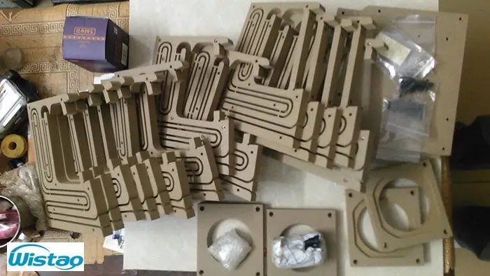

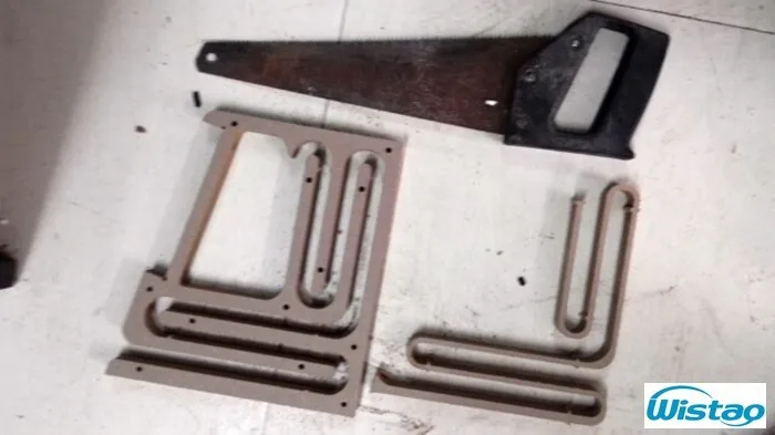
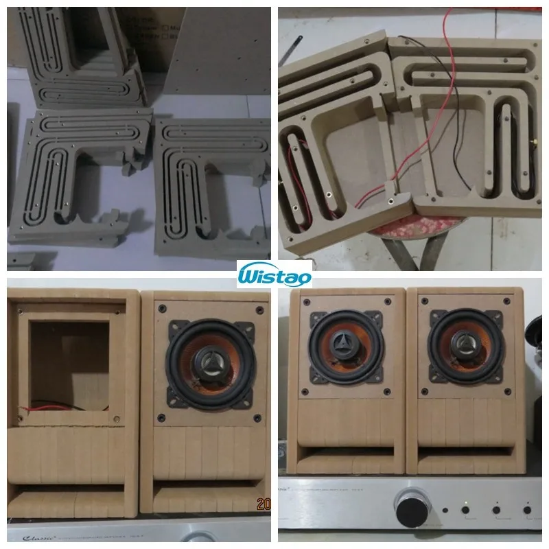
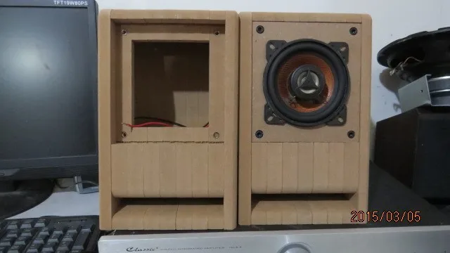
The high-density surface is smooth, seamless laminated without glue, glue also has a thickness of multi-layer stack will increase a few millimeters that lead to the panel will become small, screw holes will not be reached.
It is a pair very popular labyrinth speaker cabinet DIY kits, which adopt double back guide pipe, its return passage measured 1.6 meters, and sound quality is relatively pure. Its panel can be replaced if you have spares. This speaker cabinet kits support 2.5—4 inches full range speaker.
All kits Material: plate is HDF rather than MDF; fasteners are made of industry 8.8 level black hex bolts, lock nuts are made of Brass, fastening nuts of panel is made of steel-plated color zinc. Accessories excluded terminals and wiring. And its cross weight is about 9kg.
 |
| IWISATO 4-inch HIFI Speaker Empty Cabinet Kits |
 |
| Exploded view of Labyrinth Speaker with IWISATO 4-inch HIFI Speaker Empty Cabinet Kits |
 |
| Front panel and the body of speaker |
 |
| Inside Structure of Labyrinth Speaker |
 |
| Exploded view of side plate and front panel, body |

 |
| Fixed screw and speaker cabinet |
There are assembling steps as below and using the last version speaker cabinet as an example.
1. Please check if the shipments are completed, and placed separately firstly.
2. Use a steel saw blade (or a saw) to cut the inner ribs (waste) from the plywood sheet down, or rip them off, then use a chisel, rasp or sanding wood it that left over burrs.
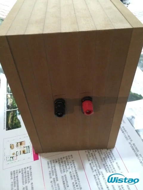
3. Install the connecting wire terminal (If there are not holes, please drill hole to fit terminals), prepare to soldering cables are not shorter than 55 cm, and soldering it to the terminal with spare.
4. Start assembling them with. Black hex bolts, lock nuts
5. After assembled, polish and smooth the external surface.
6. Install the panel, and soldering the cables to speaker units.
At the same time, please avoid moisture.
Mode details, please visit https://www.iwistao.com/collections/empty-woodem-cabinets/products/iwistao-hifi-speaker-empty-cabinet-kits-labyrinth-structure-with-high-density-fibreboard-for-2-5-4-inches-full-range-speaker-unit?variant=18118295257203
Or you may select from the collection below.
Or you may select from the collection below.
Friday, January 4, 2019
How to measure and calculate output power of power amplifier
How
to measure and calculate output power of power amplifier
There are three output powers commonly
used, rated output power, maximum output power and music power. Here is tube
amplifier as an example.
1. Rated output power (RMS): When
power amplifier frequency characteristic and harmonic distortion coefficient
can reach the specified technical specifications (generally tube power
amplifier distortion should be less than 1%), power amplifier can work continuously
for a long time safe continuous sinusoidal signal power.
2. Maximum output power (PM): it can
meet the basic parameters that Maximum output power of the power amplifier at
the rated load resistance.
3. Music Power (MPO): the
instantaneous power value that power amplifier can output when Input a large
dynamic music signal and keeping that there is not voltage drop of amplifier
power supply. This MPO power is typically 4 or 6 times RMS power.
The output power of tube power amplifier is
measured by output a 1 kHz sine wave signal from audio
signal generator to input to power amplifier to be measured through the
attenuator, and send to input end of the measured channel is placed at the
maximum position, and other channels are placed at the minimum position, and its
tone control is placed at normal position as shown. Then connect a distortion
measuring instrument to output terminal of rated load, increase input signal
voltage, make the harmonic distortion coefficient of output voltage reach the corresponding
specified value, and finally measure the output power under normal operation and
continuous signal.
 |
| How to measure and calculate output power of power amplifier |
Output power measurement method
block diagram
The output power is calculated as:
P=U2/RL.
If the power amplifier is placed
under an 8 ohm load and its output signal voltage is 20v and the distortion
factor is 1%, so its rated output power (RMS) of the amplifier is
P= U2/ RL =202/8=50W
In addition, in order to simplify
the method of output power of tube power amplifier measurement, we can use the
method shown in the figure below to make measurements. The specific method is, placing
the measured work in a normal working state, the volume potentiometer is placed
at the maximum position, and the music signal output form CD player or the
record player or the signal of 1 kHz signal generator self-made is input to the
input end of the measured power amplifier, is connected to an 8 ohm speaker or
an 8 ohm load resistor at output end of tube power amplifier, and the dynamic
voltage across the load is measured by an AC voltmeter or a multimeter AC 20V gear.
The average of measured value is its output voltage.

If a tube power amplifier is placed
at both ends of the speaker load and the output AC voltage is measured as 10v,
the estimated power of its power amplifier is
P= U2/ RL = 102/8=12w
Subscribe to:
Posts (
Atom)