IWISTAO Blog is the official platform of IWISTAO HIFI MINIMART, dedicated to high-fidelity audio and DIY electronics. We focus on tube amplifiers, output and power transformers, speaker enclosures, and Bluetooth audio technologies, including HiFi Bluetooth speakers, headphones, and tube-based acoustic systems. The blog shares product insights, technical knowledge, and practical guides for audiophiles and audio builders worldwide.
DIY Tube Amplifier Testing and Adjustment --A Practical Engineering Guide
Published by IWISTAO
Building a DIY tube amplifier is never just about getting sound. True performance, reliability, and tube longevity depend on systematic testing and precise adjustment.
Improper setup may lead to shortened tube life, unstable bias, excessive transformer heating, or even catastrophic failure. This article provides a complete, practical workflow for testing and tuning DIY tube amplifiers, suitable for both single-ended (SE) and push-pull (PP) designs.
1. Pre-Power-On Inspection (Mandatory)
Before connecting the amplifier to mains power, every circuit must be carefully inspected. Even a small wiring error can cause:
Output tube damage
Electrolytic capacitor failure
Burned power or output transformers
1.1 Visual and Wiring Checks
Correct polarity of all electrolytic capacitors
Proper orientation of rectifier tubes or diode bridges
No accidental grounding of output transformer primary
Clear separation of signal ground and protective earth (PE)
Presence of grid-leak and screen-grid resistors
Practical experience: More than 80% of first power-up failures originate from power-supply wiring or grounding mistakes.
More details about grounding, please refer to the post below.
Single-Ended (SE) and Push-Pull (PP) Tube Amplifiers
Bias adjustment is one of the most critical procedures in tube amplifier setup. In real-world engineering practice, incorrect bias accounts for a large percentage of tube failures, excessive distortion, transformer overheating, and unstable operation.
This article provides a practical, engineering-oriented guide to EL34 bias adjustment, covering both single-ended (SE) cathode bias and push-pull (PP) fixed bias amplifiers.
1. What Is Bias in a Tube Amplifier?
Bias defines the idle operating point of a vacuum tube when no audio signal is present. Electrically, it determines idle current, grid-to-cathode voltage, and static plate dissipation.
A correctly biased EL34 operates within its safe dissipation limits and in a linear region of its transfer characteristics. An incorrectly biased tube will either run too cold (increased distortion) or too hot (red plating and shortened tube life).
2. EL34 Single-Ended (SE) — Cathode Bias
Most EL34 single-ended amplifiers use cathode (self) bias. A power resistor between the cathode and ground automatically generates the required bias voltage as current flows through the tube.
(The testing point with red voltage just for you information)
2.1 Key Bias Nodes in a Real EL34 SE Schematic
Plate (Anode): typically 380–430 V (used for dissipation calculation)
Cathode (Vk): typically 30–40 V (primary bias measurement point)
Control grid (G1): near 0 V DC via grid-leak resistor
2.2 Bias Calculation (EL34 SE)
Ik = Vk / Rk
Pplate ≈ (B+ − Vk) × Ik
For long-term reliability, most EL34 SE amplifiers operate with 18–22 W plate dissipation.
3. EL34 Push-Pull (PP) — Fixed Bias
While EL34 SE amplifiers prioritize simplicity and stability, most EL34 push-pull (PP) amplifiers use fixed bias to achieve higher output power and efficiency.
3.1 Essential Bias Subsystems in EL34 PP Amplifiers
Negative bias supply (−Vbias): typically −40 to −55 V
Bias adjustment network: potentiometer distributing bias to each EL34 grid
Cathode structure: near ground, often with 1 Ω sense resistors for measurement
3.2 Bias Adjustment Targets (EL34 PP)
Typical operating conditions:
B+ ≈ 400–430 V
Idle current: 35–45 mA per tube
Plate dissipation: approximately 60–70% of maximum rating
4. IWISTAO Reference Bias Windows
EL34 SE (Single-Ended)
B+: 400–420 V
Rk: 470 Ω / 10 W
Ik: 65–75 mA
Plate dissipation: 18–22 W
EL34 PP (Push-Pull, Fixed Bias)
B+: 410–430 V
−Vbias: −42 to −50 V (adjustable)
Idle current: 38–42 mA per tube
Channel matching: within ±5%
5. EL34 Bias Adjustment Checklist
Before Power-On
Verify cathode bypass capacitor polarity (SE)
Confirm −Vbias presence and range (PP)
Ensure control grids are not positive
After Warm-Up
No red plating
Bias current within target range
Push-pull tubes closely matched
Conclusion
Bias adjustment in tube amplifiers is not a tuning trick—it is a fundamental engineering requirement.
In EL34 single-ended amplifiers, bias is established by design. In EL34 push-pull amplifiers, bias must be set and maintained by the engineer.
The following references were consulted for circuit topology, biasing practice, operating limits, and schematic conventions used in this article. All sources are publicly available and widely regarded as authoritative within the tube amplifier engineering community.
1. EL34 Datasheets & Tube Operating Limits
Mullard EL34 Datasheet (Original Reference)
Primary source for EL34 maximum plate dissipation, bias recommendations, and characteristic curves
You may optionally add the following note at the end of your blog:
All schematics shown are used for educational and technical reference purposes. Component values and operating points should always be verified against the specific amplifier design and transformer ratings before implementation.
The Sound of Power: A Deep Dive into Triode vs. Ultralinear Tube Amp Outputs
The Sound of Power: A Deep Dive into Triode vs. Ultralinear Tube Amp Outputs
Introduction: The Heart of the Tube Amp Sound
In an era dominated by digital precision and solid-state efficiency, the vacuum tube amplifier persists as an object of fascination and desire for audiophiles worldwide. Its enduring appeal lies not in perfect measurements, but in its ability to reproduce music with a characteristic warmth, richness, and emotional engagement that many find uniquely compelling. This "tube sound" is the product of a complex interplay of components, but no single part of the amplifier is more critical to shaping its final voice and performance than the power output stage.
This is where the delicate, low-level audio signal is transformed into a potent force capable of moving the cones of a loudspeaker to create sound. It is the heart of the amplifier, defining its power, its control, and much of its sonic character. For many of the most popular and versatile modern tube amplifiers—especially those built around powerful pentode or beam tetrode tubes like the iconic KT88, EL34, or 6L6—designers and listeners are presented with a fundamental choice between two primary modes of operation: Triode and Ultralinear.
This choice is not merely a technical footnote; it represents a philosophical fork in the road of audio reproduction. One path prioritizes sonic purity and textural nuance, while the other champions power and dynamic authority. This article will demystify these two modes, exploring their historical origins, technical underpinnings, and profound impact on the listening experience. By comparing their strengths and weaknesses, we will unravel the trade-offs involved, helping you understand which sound of power might be right for you.
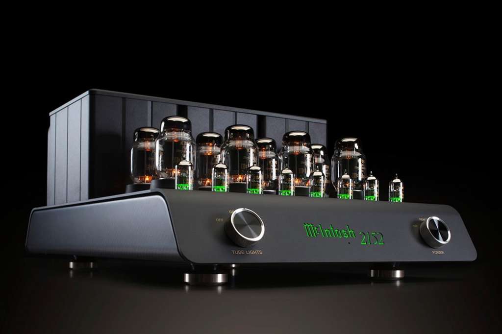
The glowing tubes of a modern high-fidelity amplifier, such as this McIntosh MC2152, are central to its sonic character and aesthetic appeal
The Foundations: A Quick Look at the Output Stage
Before we can compare Triode and Ultralinear operation, it's essential to understand the components and principles at play. The magic of these modes happens within the output stage, a circuit whose design philosophy starts at the speaker and works its way backward to the tubes themselves .
The Role of the Output Stage
In the simplest terms, the output stage is the muscle of the amplifier. The journey of an audio signal begins at a source like a turntable or DAC, where it is a very weak electrical signal. The preamplifier (or input/driver stage of an integrated amplifier) boosts this signal's voltage, but it still lacks the electrical current needed to do the physical work of moving a speaker cone back and forth. The output stage's job is to take this amplified voltage signal and add significant current, creating the power (measured in watts) required to drive the demanding, reactive load of a loudspeaker .
The Tubes at the Center
The type of vacuum tube used in the output stage is the primary determinant of its potential. While countless variations exist, the choice between Triode and Ultralinear modes hinges on the evolution from the simplest amplifying tube to more complex and powerful designs.
The Triode: Purity in Simplicity
The triode is the original and most fundamental amplifying vacuum tube. As its name suggests, it contains three primary electrodes within its glass envelope: a cathode that emits electrons when heated, a plate (or anode) that collects them, and a control grid in between that modulates the flow of electrons . By applying the small audio signal to the grid, a much larger replica of that signal is produced at the plate. Triodes, like the legendary 300B or 2A3, are celebrated for their inherent linearity. They amplify with very low distortion, producing a sound that is often described as pure, natural, and musically consonant. However, their elegant simplicity comes with a significant drawback: they are relatively inefficient and produce very little power.
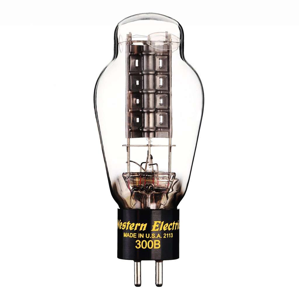
The Western Electric 300B, a classic directly heated triode tube revered for its sonic purity and linearity
The Pentode & Beam Tetrode: The Quest for Power
To overcome the power limitations of the triode, engineers introduced additional grids. The pentode adds two more: a screen grid and a suppressor grid. The beam tetrode, such as the KT88 or 6L6GC, uses carefully aligned grids and beam-forming plates to achieve a similar effect. The most important of these additions for our discussion is the screen grid (Grid 2), placed between the control grid and the plate.
By applying a stable, high positive voltage to the screen grid, it acts as an electrostatic shield, isolating the control grid from the plate and dramatically accelerating the electrons toward the plate. This innovation had a profound effect: it massively increased the tube';s efficiency and power output . However, this quest for power came with trade-offs. Pentodes and beam tetrodes are inherently less linear than triodes, producing more distortion and having a much higher internal output impedance. It is this powerful yet compromised nature of the pentode that set the stage for the development of Triode and Ultralinear modes as ways to tame and refine its performance.
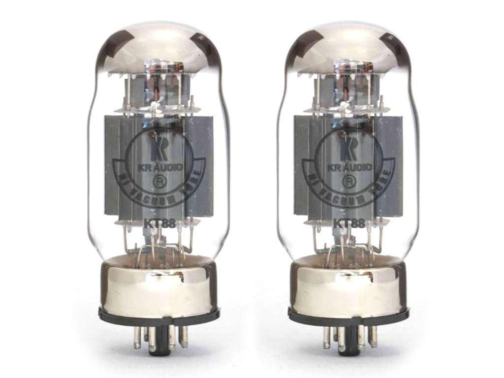
The KT88, a powerful beam tetrode tube, whose complex grid structure allows for high power output and versatile operation in modes like Ultralinear and Triode
The Contenders: Defining the Operating Modes
The ability to operate a pentode or beam tetrode in either Triode or Ultralinear mode stems from how its screen grid is connected. This single wiring choice fundamentally alters the tube's behavior and sonic signature.
Triode Mode: The Path of Purity
The simplest way to refine the sound of a pentode is to make it behave like its simpler ancestor. This is achieved through a configuration known as ";triode-strapping."
Technical Configuration
In Triode mode, the screen grid of the pentode/tetrode is connected directly to its plate (anode), often through a small-value resistor to prevent oscillation . This effectively ties the screen grid';s voltage directly to the plate's voltage. The suppressor grid (in a pentode) is typically connected to the cathode.
Core Principle
By strapping the screen to the plate, the screen grid no longer holds a stable, high DC voltage. Instead, its voltage fluctuates in perfect lockstep with the audio signal present on the plate. This forces the complex five-element tube to mimic the electrical characteristics of a three-element triode. It inherits the triode's high linearity and low output impedance, but also its low efficiency and power output . In essence, you are trading the pentode's raw power for the triode's sonic refinement.
Ultralinear (UL) Mode: The "Best of Both Worlds"?
If Triode mode represents a return to classic simplicity, Ultralinear mode is a clever and sophisticated compromise, born from a desire to have the best of both worlds.
Historical Context
The Ultralinear circuit was devised and patented in 1951 by two American engineers, David Hafler and Herbert Keroes. In a seminal paper published in *Audio Engineering* magazine, they outlined a new method of operating pentode tubes that aimed to cure the ills of both pure triode and pure pentode operation . They sought a middle ground that could offer the power of a pentode with the low distortion and low output impedance of a triode.
Technical Configuration
Instead of connecting the screen grid to a steady DC supply (pentode mode) or directly to the plate (triode mode), the Ultralinear configuration connects the screen grid to a specific tap on the primary winding of the output transformer. This tap is typically located at a point that represents 40% to 43% of the primary winding';s turns . This is why a high-quality output transformer designed specifically for UL operation is absolutely essential.
Core Principle
This configuration creates a unique form of localized feedback. Because the screen grid is connected partway up the transformer primary, it receives a certain percentage (e.g., 40%) of the plate';s output signal swing. This signal is in anti-phase to the input signal at the control grid. This feedback simultaneously lowers the tube's gain, distortion, and output impedance, pushing its characteristics away from the pentode profile and towards the triode profile. Hafler and Keroes argued that this wasn't just a simple compromise, but a new, "ultra-linear" operating point that could potentially offer performance superior to both extremes .
Key Takeaways: Defining the Modes
Triode Mode: Achieved by connecting the screen grid to the plate. It forces a pentode to behave like a triode, prioritizing low distortion and linearity at the expense of power.
Ultralinear Mode: Achieved by connecting the screen grid to a special tap on the output transformer. It creates a hybrid mode with characteristics between a triode and a pentode, aiming for high power with low distortion.
Head-to-Head: The Ultimate Comparison of Triode vs. Ultralinear
With the technical foundations established, we can now directly compare how these two modes perform in the areas that matter most to an audiophile: power, sound, distortion, and speaker control.
Power Output & Headroom
This is the most straightforward and dramatic difference between the two modes. In the contest of raw power, Ultralinear is the undisputed champion.
An amplifier switched from Triode to Ultralinear mode will often see its maximum power output double. For example, the popular Cary SLI-80 integrated amplifier is rated at 40 watts per channel in Triode mode, but a formidable 80 watts per channel in Ultralinear mode . Measurements of other well-known amplifiers confirm this trend:
Manley Stingray iTube: 18W (Triode) vs. 30W (UL) into 8 ohms.
Manley Mahi Monoblocks: 20W (Triode) vs. 40W (UL).
PrimaLuna EVO 400: 37W (Triode) vs. 67W (UL) into 4 ohms.
The implication for the listener is significant. Higher power translates to greater headroom—the ability of an amplifier to handle sudden musical peaks (like a cymbal crash or a powerful drum hit) without distorting or ";clipping." Ultralinear mode is therefore far better suited for driving inefficient, low-sensitivity speakers, for filling large rooms with sound, or for listeners who enjoy high volume levels and the unrestricted dynamics of large-scale music.
Sonic Signature & Musical Presentation
Beyond the numbers, the choice between Triode and Ultralinear profoundly affects the character and "feel" of the music. This is where listener preference becomes paramount, as each mode presents a distinct and valid interpretation of the audio signal.
Triode: The Sound of Intimacy and Nuance
Listeners and reviewers consistently use a specific vocabulary to describe the sound of Triode mode. Words like "sweet," "smooth,"; "liquid," and "holographic" appear frequently. One listener on the diyAudio forum notes that with his KT88 tubes, "triode mode is more smooth" . Another on the Audiogon forum elaborates:
"Triode will sacrifice the power for a greater sense of dimension, space and textural nuance. Ultra linear leaves me with the impression of sitting much further back in the performance, while triode brings me in closer and gives me a better sense of where the instruments are on stage."
Triode mode excels at rendering the subtle details, textures, and micro-dynamics that create a sense of realism and presence. It tends to create a deep, three-dimensional soundstage where instruments and vocalists have a palpable, ";in-the-room" quality. This makes it a favorite for genres that thrive on intimacy: vocals, jazz quartets, chamber music, and acoustic performances.
Ultralinear: The Sound of Energy and Authority
The sonic signature of Ultralinear mode is one of power and control. It is often described as "punchy," ";dynamic," ";vibrant," and "energetic." It delivers music with a greater sense of force and impact. One listener describes the sound as "vibrant and full of sparkle," noting that "cymbals sound wonderful" . Another notes that UL mode has "loads of energy and punch."
This presentation gives Ultralinear an edge with high-energy music. It can handle the scale and complexity of a full orchestra, the driving rhythm of a rock band, or the deep bass lines of electronic music with an authority that Triode mode can struggle to match. The bass is often perceived as tighter and more impactful, and the high frequencies can have more "sparkle" and excitement.
Distortion & Linearity
The discussion of distortion is where things become more complex and nuanced. The common wisdom holds that triodes are simply more linear and have lower distortion.
A triode's characteristic curves—the graphs that show its response—are more evenly spaced and parallel than a pentode';s, indicating a more linear (and thus lower distortion) amplification process . Furthermore, the distortion a triode does produce is dominated by the simple and musically pleasant second-order harmonic, which can add a sense of warmth and richness. Pentodes, in contrast, produce a more complex mix of higher-order harmonics (3rd, 5th, etc.), which can sound harsher to the human ear.
Ultralinear mode, through its feedback mechanism, significantly reduces this pentode-like distortion. The original Hafler and Keroes paper claimed that at an optimal tap point (around 43%), distortion could be even lower than in triode mode. Some data supports this, with datasheets for tubes like the EL84 showing total harmonic distortion (THD) and intermodulation distortion (IMD) values for Ultralinear that are lower than for either pure pentode or triode operation .
However, the real-world implementation is key. The quality of the output transformer is paramount. Furthermore, some modern designs may alter the amount of global negative feedback when switching modes. For instance, a review of the EAT E-Glo i amplifier noted that to compensate for the gain loss in triode mode, the designers reduced the negative feedback, which actually resulted in slightly *higher* measured distortion in triode mode compared to UL mode . This highlights that one cannot make a blanket statement; the final distortion profile is a product of the entire amplifier design, not just the operating mode itself.
Output Impedance & Damping Factor
Output impedance is a measure of how "stiff" the amplifier's output is—its ability to act as a pure voltage source. A lower output impedance is generally better, as it allows the amplifier to exert more control over the speaker.
This control is quantified by the Damping Factor, which is the ratio of the speaker's impedance to the amplifier's output impedance. A higher damping factor means the amplifier can better control the speaker's woofer, forcing it to stop moving when the signal stops. This leads to tighter, more articulate, and less "boomy" bass.
Triode Mode: Characterized by a naturally low output impedance and thus a high damping factor. This contributes to its reputation for well-defined, articulate bass and excellent speaker control .
Ultralinear Mode: Has a higher output impedance than triode mode (though much lower than pentode mode). This results in a lower damping factor. The effect on bass can be speaker-dependent, sometimes sounding slightly looser or fuller, which may or may not be desirable depending on the system and listener preference.
Key Takeaways: Head-to-Head Comparison
Attribute
Triode Mode
Ultralinear Mode
Power Output
Low (e.g., 20-40W)
High (e.g., 40-80W), often double the Triode power
Sonic Character
Sweet, smooth, liquid, holographic, detailed
Punchy, dynamic, vibrant, powerful, energetic
Best For
Vocals, jazz, acoustic, intimate music
Rock, orchestral, complex music, high volumes
Distortion
Inherently low, musically consonant (2nd order)
Low (compromise), highly dependent on transformer quality
Damping Factor
High (tighter bass control)
Lower (fuller, potentially looser bass)
Practical Considerations for the Audiophile
Understanding the technical differences is one thing; applying that knowledge to your own system and listening habits is another. Here are some practical factors to consider.
Which Mode is Right for My System?
The "best" mode is not absolute; it's relative to your other components and your personal taste.
Based on Speakers: This is the most critical factor. If you own speakers with low sensitivity (typically rated below 88dB), the high power of Ultralinear mode is almost a necessity to drive them properly and avoid clipping. Conversely, if you have high-sensitivity speakers (e.g., 95dB or higher), they require very little power, giving you the freedom to enjoy the subtle nuances of the lower-powered Triode mode without compromise.
Based on Music Taste: Your music library is a strong guide. If you spend most of your time listening to intimate vocal performances, small jazz ensembles, or acoustic folk, the holographic soundstage and textural detail of Triode mode will likely be more rewarding. If your playlists are filled with Led Zeppelin, Mahler symphonies, or Daft Punk, the power, punch, and dynamic headroom of Ultralinear mode will bring that music to life.
The Luxury of Choice: Fortunately, many modern integrated amplifiers, like the Willsenton R8, include a simple switch on the unit or remote control that allows the user to toggle between Triode and Ultralinear modes on the fly . This offers the ultimate flexibility, allowing you to choose the mode that best suits the specific album, track, or even your mood at that moment.
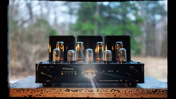
Modern amplifiers like the Willsenton R8 often feature a switch to toggle between Triode and Ultralinear modes, offering listeners the best of both worlds
The Impact on Tube Longevity
A common question among tube amp owners is whether one mode wears out the expensive output tubes faster than the other. The prevailing wisdom, supported by amplifier designers, is that there should be no significant difference in tube life expectancy.
In a well-designed amplifier, the key parameters that affect tube wear—the plate voltage, screen voltage, and bias current—are set to be very similar in both modes. As one expert on the Dynaco Tube Audio forum explains, ";Voltages on the screens and the plate will be basically unchanged and the bias point will be pretty much the same... The B+ voltage is also basically the same no matter which mode you have the amp set in" . Therefore, under identical listening conditions, a tube should last just as long in either mode.
There is, however, a practical nuance. If you are consistently pushing the amplifier to its volume limits to achieve a desired loudness, doing so in the lower-powered Triode mode will drive the tubes into clipping and saturation much earlier and more often. This state of being constantly overdriven could arguably be more stressful on the tubes than running the amplifier at the same volume in the higher-powered UL mode, where it would still have plenty of headroom. An amp running hard in Triode mode may run hotter than the same amp running comfortably in UL mode at the same sound pressure level .
The Critical Role of the Output Transformer
It is impossible to overstate the importance of the output transformer (OPT) in this discussion, especially for Ultralinear operation. The OPT is arguably the most critical, complex, and expensive component in a tube amplifier after the tubes themselves. Its job is to take the high-voltage, low-current signal from the tubes and convert it into a low-voltage, high-current signal suitable for driving speakers.
For Ultralinear mode, the OPT's job is even more complex. The performance of the UL circuit is entirely dependent on the quality of the transformer's windings and the precise placement of the screen taps. A poorly designed transformer with improperly placed taps or poor coupling between the screen and plate windings will fail to realize the benefits of the UL circuit, resulting in compromised performance that may sound inferior to both triode and pure pentode modes . As one source puts it, "Transformers are the loose cannons of an amplifier's design." This is why high-quality tube amplifiers, especially those offering a well-implemented Ultralinear mode, invest heavily in custom-wound, oversized output transformers.
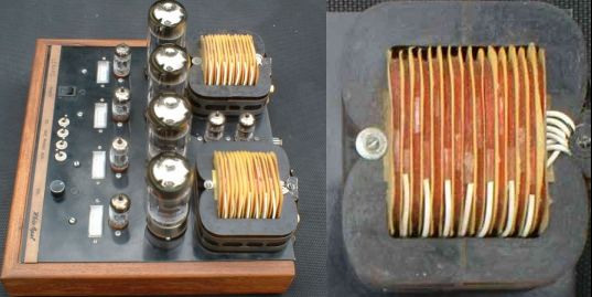
The output transformer (right) is a critical component whose quality and design, including the placement of screen taps, dictates the performance of the Ultralinear circuit
Conclusion: The Power of Personal Preference
The debate between Triode and Ultralinear operation is not a battle with a single winner. It is a classic engineering trade-off, a balance of competing virtues. The choice encapsulates the very essence of high-fidelity audio, where technical specifications and subjective experience intertwine.
To summarize the central conflict: Triode mode offers a path of sonic purity, delivering unparalleled nuance, textural detail, and a holographic soundstage, but at the significant cost of power and dynamic headroom. Ultralinear mode provides that missing power, serving up a punchy, authoritative, and dynamic presentation that can drive almost any speaker with ease, with a slight sacrifice in the ultimate refinement and intimacy of the triode sound.
Ultimately, there is no universally "better" mode. The ideal choice is deeply subjective and depends entirely on the listener's priorities. It is a decision guided by your speakers, your room, your musical tastes, and what you, personally, value most in the reproduction of sound. Do you crave the feeling of a singer standing in your room, or the physical impact of a kick drum? Do you want to hear every subtle breath, or feel the full force of a symphony orchestra?
The very existence of this choice is a testament to the ingenuity and versatility of classic tube amplifier design. It provides a powerful tool for audiophiles to tailor the sound of their system to their exact preferences. If you ever have the opportunity to audition an amplifier with this feature, be sure to explore both modes extensively. In the end, the only "right" answer is the one that sounds best to your own ears and connects you more deeply to the music you love.
References
[1]
[PDF] The Tube CAD Journal,Ultra-Linear Output Stages - Pearl HiFi