Design Principles of 2-Way Phase-Inverted Loudspeakers
I. Introduction: The Allure and Advantage of 2-Way Bass-Reflex Speakers
The world of do-it-yourself (DIY) audio offers a unique blend of technical challenge, creative expression, and profound satisfaction. Building your own loudspeakers, in particular, provides an unparalleled learning experience. It allows enthusiasts to delve into the science of sound reproduction, customize performance to their liking, and often achieve a performance-to-cost ratio that commercial offerings can struggle to match. Among the myriad design choices, the 2-way phase-inverted (or bass-reflex) loudspeaker stands out as a popular and rewarding project for both novices and experienced builders.
Defining the 2-Way Phase-Inverted Loudspeaker
This loudspeaker configuration is characterized by two primary features:
- 2-Way System: This refers to the division of the audio spectrum between two types of specialized drivers. A larger driver, the **woofer**, is dedicated to reproducing low and often midrange frequencies. A smaller driver, the **tweeter**, handles the high frequencies (Aulart). This separation allows each driver to operate within its optimal frequency range, leading to lower distortion and better overall sound quality than a single full-range driver attempting to cover the entire spectrum.
- Phase-Inverted (Bass-Reflex/Ported) Enclosure: This type of enclosure features an opening, known as a port or vent, which includes a tube connecting the internal air volume to the outside environment. The fundamental principle is to utilize the sound wave generated by the rear of the woofer cone. Instead of simply absorbing or blocking this rear wave (as in a sealed enclosure), the port is precisely tuned to control its phase. Around a specific low frequency (the tuning frequency), the port radiates sound that is in phase with the woofer's front wave. This effectively reinforces the low-frequency output. The enclosure and port act as a Helmholtz resonator (Audio Judgement), where the air in the port acts as a mass and the air in the enclosure acts as a spring.
Key Advantages of this Configuration
The 2-way bass-reflex design offers several compelling advantages:
- Enhanced Low-Frequency Extension: Compared to a sealed enclosure of similar size using the same driver, a bass-reflex system can typically produce deeper bass. The port's output effectively extends the system's response to lower frequencies (Castells, riunet.upv.es).
- Potentially Higher Bass Efficiency: In its tuned frequency range (around the port resonance), the system can deliver more bass output for the same amount of amplifier power. This is because both the woofer and the port contribute to the sound output (Audio Judgement).
- Good Balance for DIY: This configuration often represents an excellent compromise between achieving satisfying bass performance, maintaining a manageable enclosure size, and keeping the design complexity within reach for DIY projects. While more complex to design accurately than a sealed box, the potential rewards in bass output are significant.
Roadmap for This Guide
Embarking on a 2-way bass-reflex loudspeaker project requires understanding several interconnected design aspects. This guide will walk you through the essential stages:
- Foundations: Understanding the core components – drivers, enclosure materials, and crossover networks.
- The Blueprint: A step-by-step workflow detailing driver selection, enclosure volume and port tuning calculations, and the critical process of crossover network design.
- From Theory to Reality: Practical tips and considerations for construction, initial testing, and methods for refinement, both with and without measurement tools.
- Concluding Principles: A summary of key interactions and resources for further exploration in your audio journey.
Let's dive into the fascinating world of loudspeaker design.
II. Foundations: Understanding Your Loudspeaker's Anatomy
A loudspeaker system is more than just a collection of parts; it's a carefully engineered electro-acoustic system where each component plays a vital role. Understanding these components and their interplay is fundamental to designing a successful 2-way bass-reflex speaker.
A. The Drivers: Heart of the Sound Reproduction
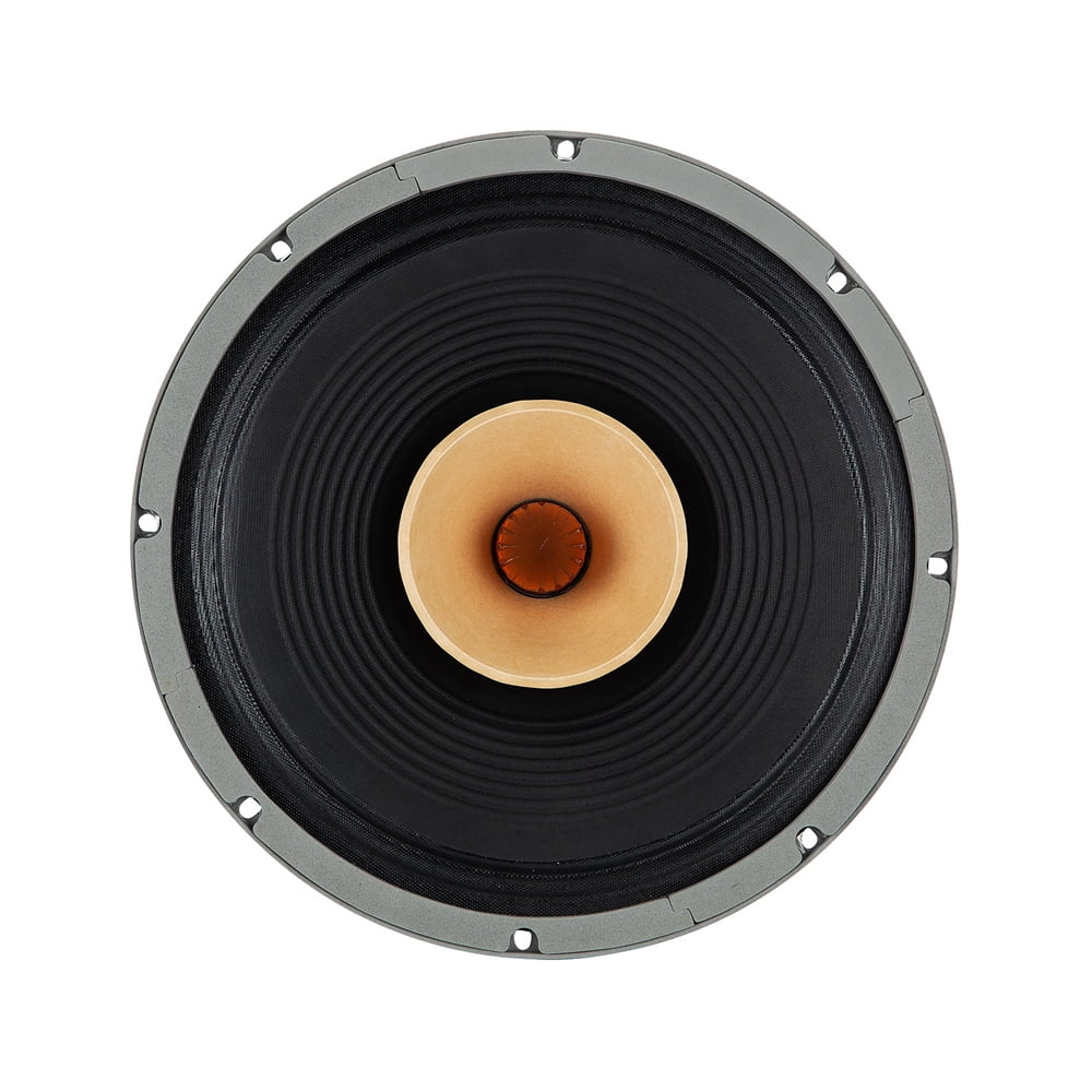
Drivers are the electromechanical transducers that convert electrical audio signals from your amplifier into audible sound waves. In a 2-way system, we use two specialized types.
1. Woofer (Low/Mid-Frequency Driver)
Role: The woofer is responsible for reproducing the lower end of the audio spectrum, typically from the deep bass notes up through the midrange frequencies. It forms the foundational weight and body of the sound (Aulart).
Critical Thiele/Small (T/S) Parameters for Ported Designs: These electromechanical parameters, pioneered by A.N. Thiele and Richard H. Small, are essential for predicting a driver's low-frequency performance in an enclosure (Wikipedia - Thiele/Small parameters). For ported designs, several are particularly crucial:
Fs (Free-Air Resonance): This is the natural frequency at which the driver's moving mass will resonate when suspended in free air (i.e., not in an enclosure). It's a primary input for enclosure modeling software and calculations (Mynewmicrophone).Qts (Total Q-factor): This parameter describes the driver's overall damping at its resonant frequency, considering both electrical (Qes) and mechanical (Qms) damping. Drivers with lower Qts values (e.g., less than 0.5, ideally below 0.4 for classic ported alignments) are generally better suited for bass-reflex enclosures, as they tend to have better control and less "boominess" (MISCO Speakers).Vas (Equivalent Compliance Volume): This represents a volume of air that has the same acoustic compliance (springiness) as the driver's suspension (surround and spider). It directly influences the required enclosure volume; a larger Vas typically means a larger box is needed for a given tuning (Zhihu - T/S Parameters).
Other Important Woofer Parameters:
Xmax (Maximum Linear Excursion): This indicates how far the woofer cone can travel in one direction while maintaining a linear relationship between input signal and output (i.e., before distortion rises sharply). It's crucial for determining the maximum low-frequency output capability of the speaker (Sound-AU - Enclosures).Pe (Thermal Power Handling): This specifies the maximum continuous electrical power the voice coil can dissipate as heat before being damaged.SPL @ 1W/1m (Sensitivity): This measures how loud the driver plays (in decibels, dB) with 1 watt of electrical input, measured at a distance of 1 meter. It's important for overall system efficiency and for matching the woofer's output level with the tweeter.
Woofer Selection Criteria for Ported Enclosures:
- Efficiency Bandwidth Product (EBP): Calculated as
Fs / Qes. This figure provides a quick indication of a driver's suitability for sealed versus ported enclosures.- EBP values roughly between 50 and 90 can often work well in ported enclosures, offering a good balance of bass extension and transient response.
- EBP values greater than 90-100 generally indicate a driver well-suited for ported designs, often aiming for high efficiency_or_ extended bass in such a setup. Drivers with EBP < 50 are usually better for sealed enclosures.
- Lower
Qts values (e.g., < 0.5, ideally <0.4) are generally preferred for classic, well-behaved ported alignments. - Sufficient
Xmax is needed to achieve the desired low-frequency output levels without excessive distortion or bottoming out.
2. Tweeter (High-Frequency Driver)
Role: The tweeter is designed to reproduce the upper range of audible frequencies (treble), contributing to the sound's detail, clarity, "airiness," and spatial cues (Aulart).
Key Tweeter Parameters:
Fs (Resonant Frequency): This is the tweeter's own free-air resonant frequency. It's a critical parameter because the crossover frequency (Fc) chosen for the system *must* be significantly higher than the tweeter's Fs. A common rule of thumb is to set Fc at least 1.5 to 2 octaves above the tweeter's Fs (e.g., if tweeter Fs is 1kHz, Fc should be at least 2kHz, preferably 2.8kHz or higher) (Speakerwizard). Operating a tweeter too close to its Fs can lead to high distortion and potential damage.Power Handling: This indicates how much power the tweeter can handle. In a 2-way system, the crossover network protects the tweeter from low-frequency energy, which carries most of the power, so tweeter power handling needs to be adequate for the high-frequency portion of the signal.Sensitivity (SPL @ 1W/1m): Similar to the woofer, this measures the tweeter's output level for a given input. Ideally, the tweeter's sensitivity should match or be slightly higher than the woofer's. If it's higher, attenuation (typically using an L-pad resistor network) will be required in the crossover to balance its output with the woofer (Audioholics).Dispersion: This describes how widely and evenly the tweeter spreads high frequencies into the listening area. Wider and more consistent dispersion is generally desirable for a larger "sweet spot" and more natural soundstage.
Tweeter Selection Criteria:
Fs well below the intended crossover point (as discussed above).- A smooth and extended frequency response within its designated operating range.
- Dispersion characteristics that integrate well with the woofer at the chosen crossover frequency to provide even coverage.
- Sensitivity that allows for proper level matching with the woofer, either directly or via attenuation.
B. The Enclosure (Cabinet): Shaping the Bass Foundation
The loudspeaker enclosure, or cabinet, is far more than just a box to hold the drivers. It plays a critical acoustic role, especially in determining the bass performance.
Fundamental Role:
- Acoustic Baffle: It separates the sound waves generated by the rear of the woofer cone from those generated by the front. Without an enclosure (or at least a baffle), these out-of-phase waves would meet and cancel each other out, especially at lower frequencies, resulting in very little bass output (Castells - Closed Box Design).
- Structural Support: It provides a stable and rigid mounting platform for the drivers, minimizing unwanted vibrations that can color the sound.
- Diffraction Management: The shape and size of the enclosure's front baffle influence how sound waves diffract (bend) around its edges. This "baffle diffraction" can cause ripples in the frequency response, particularly at higher frequencies.
Bass-Reflex Specifics:
- Enclosure Volume (
Vb): This is the net internal volume of air within the box (after accounting for the volume displaced by drivers, bracing, and port). Vb is a primary determinant of the system's low-frequency alignment and how the woofer interacts with the port (Audio Judgement). - Tuning Frequency (
Fb): This is the frequency at which the Helmholtz resonator (formed by the enclosure volume and the port) is tuned. At and near Fb, the port's output is maximized, reinforcing the woofer's output and extending the bass response. Below Fb, the port's output rapidly becomes out of phase with the woofer, and the system's response rolls off steeply (typically 24 dB/octave for a 4th-order bass-reflex system) (Castells - Bass Reflex Design).
Comparative Analysis: Enclosure Materials
The choice of enclosure material significantly impacts the speaker's acoustic performance, primarily by influencing how much the cabinet walls vibrate and potentially radiate sound. Ideal enclosure materials are dense, stiff, and well-damped to resist vibration and prevent coloration. (HiFiReport - Material Impact), (MISCO - Enclosure Considerations).
| Material | Typical Density (kg/m³) | Relative Stiffness | Relative Damping | Workability | Cost Indicator | Finishability | Acoustic Impact Notes |
|---|
| MDF (Medium Density Fiberboard) | ~600-800 | Good | Very Good | Easy | Low-Medium | Good (paint) | Well-damped, consistent, common choice. Heavy. Concerns about dust when cutting. |
| Plywood (e.g., Baltic Birch) | ~640-700 (Baltic Birch) | Very Good | Good | Moderate | Medium | Good (stain/paint) | Stiffer and often stronger than MDF for its weight. Fewer voids than standard plywood. Excellent for durability. |
| Solid Wood | Varies (e.g., Oak ~750) | Varies | Fair to Good | Difficult | High | Excellent | Can look beautiful, but prone to warping/cracking with humidity changes. Can resonate more than MDF/plywood; requires careful bracing and design. |
| High-Quality Particle Board | ~650-750 | Fair | Fair | Easy | Low | Fair (veneer/paint) | Less ideal than MDF due to lower consistency, stiffness, and susceptibility to moisture. Can be used if thick and well-braced for budget builds. |
| Composites (e.g., Phenolic, Corian) | Varies (often high) | Excellent | Excellent | Specialized | Very High | Varies | Top-tier acoustic performance (very inert), but difficult to work with and expensive for most DIY projects. |
Table 1: Comparison of Common Loudspeaker Enclosure Materials.
Analysis: Higher density and stiffness (Young's Modulus) in a material generally lead to reduced panel vibrations because more energy is required to excite the panel. Good internal damping within the material helps to dissipate any vibrational energy quickly, preventing the enclosure from "singing along" with the music and coloring the sound. MDF is popular because it offers a good balance of these properties at a reasonable cost. Baltic Birch plywood is favored for its superior stiffness-to-weight ratio and strength, often used in professional audio and high-end systems.
Enclosure Construction Best Practices
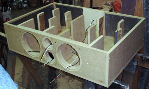
- Bracing: This is crucial for increasing panel stiffness and reducing vibrations, which in turn minimizes audible enclosure resonances and sound coloration. Techniques include perimeter braces (around the inside edges of panels), cross-braces (connecting opposite panels), and shelf braces. Asymmetric placement of braces is often recommended as it helps to break up panel resonant modes into smaller, higher-frequency, and less problematic ones (Sound-AU - Enclosures).
- Internal Damping Material: In ported enclosures, the primary role of damping material is to absorb midrange energy radiated from the woofer's rear, preventing it from reflecting inside the cabinet and potentially escaping through the woofer cone or port, which could color the sound. It also helps reduce internal standing waves. Common types include acoustic foam, polyester fiberfill (Polyfill), long-fiber wool, and specialized bituminous damping sheets. Damping material is typically applied to some or all internal walls (often excluding the baffle or the area immediately around the port entrance). Crucially, do not obstruct the port opening or significantly fill the entire enclosure volume, as this will detune the port and effectively alter
Vb, changing the bass alignment (Audio Judgement - Bass Reflex Damping). Generally, lining walls with 1-2 inches of material is a good starting point. - Airtight Seals: For a bass-reflex enclosure to function as designed (i.e., for the port to be the only significant air leak), all other joints must be airtight. Any unintended leaks act as additional, uncontrolled ports, which will detune the system and degrade performance. Use high-quality wood glue for all joints, caulk internal seams after assembly, and use gaskets (e.g., foam tape, rubber) for drivers, terminals, and any removable panels.
C. The Crossover Network: Directing the Sonic Traffic
The crossover network is an electrical filter circuit that plays a pivotal role in any multi-way loudspeaker system. Its primary functions are:
- To accurately divide the incoming audio signal from the amplifier, sending the low and midrange frequencies to the woofer and the high frequencies to the tweeter (AES E-Lib - Crossover Networks: A Review).
- To protect the tweeter from damaging low-frequency energy, which it is not designed to handle and which carries the most power (AudioControl - Crossover Networks from A to Linkwitz-Riley).
- To shape the overall frequency response and, critically, the phase response of the loudspeaker system, ensuring a smooth and coherent transition between the woofer and tweeter.
Critical Parameters:
- Crossover Frequency (
Fc): This is the specific frequency at which the division occurs. The crossover applies a low-pass filter to the woofer (allowing frequencies below Fc to pass) and a high-pass filter to the tweeter (allowing frequencies above Fc to pass). - Slope (or Order): This defines the rate at which frequencies are attenuated (reduced) beyond the crossover frequency. It's typically expressed in decibels per octave (dB/oct).
- 1st order: 6 dB/octave
- 2nd order: 12 dB/octave
- 3rd order: 18 dB/octave
- 4th order: 24 dB/octave
Steeper slopes provide better separation between drivers but introduce more phase shift and can sometimes sound less natural if not implemented carefully (SubwooferAddict - 12dB vs 24dB Slopes). - Phase Response: This refers to how the crossover affects the relative timing (phase) of the signals sent to the woofer and tweeter. Proper phase alignment between drivers at and around the crossover frequency is crucial for them to sum acoustically in a coherent manner, minimizing dips or peaks in the combined frequency response and reducing off-axis lobing (uneven sound dispersion) (TestHiFi - Loudspeaker Phase Response).
Comparative Analysis: Crossover Topologies
Several crossover filter topologies (electrical designs) are commonly used. Each has distinct characteristics regarding how the drivers sum acoustically, their phase relationships, complexity, and resulting sound. Note that the "acoustic" slope is what matters, which is a combination of the electrical filter and the natural roll-off of the drivers themselves.
| Topology | Order(s) Commonly Used | Typical Electrical Slope(s) | Summed On-Axis Acoustic Response at Fc | Driver Phase Relationship at Fc (Acoustic Target) | Polar Response (Lobing) Characteristics | Component Count / Complexity | Sound Character / Notes |
|---|
| Butterworth (BW) | 1st, 2nd, 3rd, 4th | 6, 12, 18, 24 dB/oct | Even orders sum with a +3dB peak if drivers are electrically in phase; can be flat if one driver's polarity is inverted. Odd orders sum flat with a 90° acoustic phase difference between drivers. | Even orders often require one driver's polarity to be inverted for flattest sum. Odd orders inherently have a 90° phase difference. | Can exhibit significant lobing (uneven off-axis response), especially vertically, due to phase differences. | Moderate. | Often described as "smooth." Popular, but achieving seamless summation can be tricky due to phase issues. The +3dB peak of an even-order Butterworth can be problematic unless addressed (RANE Note 147). |
| Linkwitz-Riley (LR) | 2nd, 4th (most common) | 12, 24 dB/oct (these are target acoustic slopes) | Flat. | Drivers are acoustically in-phase at Fc. This results from specific electrical phase shifts (e.g., 4th order LR has tweeter lagging woofer electrically by 360 degrees, effectively in phase). | Generally good, with minimized lobing and a symmetrical polar response when drivers are vertically aligned and coincident (or as close as possible). | Higher (an LR filter is effectively two cascaded Butterworth stages to achieve its target acoustic slopes and phase characteristics). | Considered "accurate" and well-behaved. Widely used for good on- and off-axis performance. Requires careful component selection and layout for optimal results (AES E-Lib - Crossover Networks). |
| Bessel | Less common for passive DIY; sometimes 2nd, 4th | 12, 24 dB/oct | Can be designed for a slight dip or flat response. | Aims for approximately linear phase in the passband, leading to the best transient response (time-domain behavior). | Moderate; can be good. | Moderate to High. | Known for excellent transient response and "time coherence." The phase characteristics are its main strength. However, achieving true linear phase across the crossover region with passive components and real drivers is challenging (RANE Note 147). |
Table 2: Comparison of Common Passive Crossover Topologies.
Analysis: Linkwitz-Riley (LR) crossovers are often favored for 2-way designs, especially 4th-order (24 dB/octave), due to their inherently flat summed acoustic response when drivers are connected in acoustic phase and their good off-axis behavior. However, it's crucial to remember that these ideal characteristics assume perfect drivers. In reality, the natural frequency response and phase characteristics of the chosen woofer and tweeter heavily influence the final outcome. Simulation with actual driver data is essential for optimizing any crossover design.
Passive Crossover Components: The Building Blocks
Passive crossovers use capacitors, inductors, and resistors to filter the audio signal without external power.
III. The Blueprint: Step-by-Step Design Workflow for Your 2-Way Bass-Reflex Speaker
Designing a 2-way bass-reflex loudspeaker is an iterative process that blends theory, calculation, simulation, and eventually, practical refinement. Following a structured workflow will significantly increase your chances of success.
1. Establish Clear Design Goals
This foundational step involves defining precisely what you aim to achieve with your loudspeaker project. Vague goals lead to unfocused design choices.
Considerations:
- Target Frequency Response: Define your desired low-frequency extension (e.g., the -3dB point, or F3, at 45 Hz) and high-frequency extension (e.g., 20 kHz). Aim for a generally flat response across the audible spectrum.
- Desired Sensitivity: For example, 87 dB @ 1W/1m. This will guide driver selection and influence how well the speaker pairs with different amplifiers.
- Maximum Enclosure Size/Footprint: Practical constraints based on your listening room, aesthetics, or available materials.
- Budget: Allocate funds for drivers, crossover components (capacitors, inductors, resistors), and enclosure materials (wood, damping, finish).
- Intended Application:
- Hi-Fi Music Listening: Might prioritize accuracy, smooth response, good imaging.
- Home Theater: May require higher output capabilities, robust bass for impact.
- Near-Field Monitoring (Studio): Demands very flat, uncolored response for critical listening. (Make Life Click - Studio Monitor vs HiFi) differences often lie in design philosophy: studio monitors aim for neutrality, HiFi for enjoyable sound which may include some coloration.
2. Woofer Selection & Enclosure Volume (Vb) / Tuning (Fb) Modeling
With design goals established, select a woofer whose Thiele/Small parameters (especially low Qts, suitable EBP as discussed in Part II.A) align with your objectives for a ported enclosure.
Modeling Process:
- Software (Highly Recommended): Using specialized software is paramount for accurate bass-reflex design. Popular choices include:These tools allow you to input the woofer's T/S parameters and simulate its response in different enclosure volumes and tunings.
- Iterative Approach:
- Input the selected woofer's T/S parameters into the software.
- Experiment by changing the enclosure net internal volume (
Vb) and the Helmholtz tuning frequency (Fb). - Observe the predicted outcomes: frequency response (SPL curve), port air velocity (to check for chuffing), and woofer cone excursion (to ensure it stays within Xmax limits at expected power levels).
- Goal Alignments: Aim for a recognized low-frequency alignment that suits your goals. Common ported alignments provide different trade-offs between bass extension, transient response, and group delay:
- QB3 (Quasi-Butterworth 3rd Order): Often characterized by a slight peak before roll-off, good for perceived bass impact.
- SBB4 (Sub-Chebyshev 4th Order) / BB4 (Butterworth 4th Order): Typically aim for a maximally flat response down to the cutoff frequency.
- EBS (Extended Bass Shelf): Sacrifices some mid-bass efficiency for deeper extension, often resulting in a more gradual roll-off above a lower F3. Requires careful driver selection.
The software will help you visualize these alignments. The goal is to find a Vb and Fb combination that yields the desired F3 (e.g., -3dB point) and a well-behaved response without excessive peaking or premature roll-off, while keeping excursion and port velocity in check.
Outputs: After modeling, you will have determined an optimal pair of values for Vb (e.g., 30 liters) and Fb (e.g., 40 Hz) that best meet your bass extension and response shape goals for the chosen woofer.
Figure 1: Illustrative example of a bass-reflex system simulation. Parameters: Vb=30L, Fb=40Hz. This shows SPL response, woofer excursion relative to an Xmax limit, and port air velocity. Real simulations would use specific driver data.
3. Port Design and Calculation
Once Vb and Fb are determined, the physical dimensions of the port (length Lv, and area Av or diameter Dv) must be calculated to achieve this tuning.
- Port Area (
Av) / Diameter (Dv):- Minimum Area: This is critical to prevent "chuffing" or port noise, which occurs when air velocity in the port becomes too high, especially at
Fb during loud bass passages. Software like WinISD can predict port air velocity. A general guideline is to keep peak air velocity below about 5-10% of the speed of sound (Mach 0.05 to 0.10). (Audio Judgement - Bass Reflex Speaker Design) offers rules of thumb, like port diameter being 1/3 to 1/2 of the woofer's effective diameter. - Practicality: Too small a port area leads to noise and compression (where the port can't move enough air, limiting output). Too large an area can result in an impractically long port to achieve the desired tuning frequency.
- Port Length (
Lv):- Formula (Example for a cylindrical port): The length of the port is inversely proportional to
Fb squared and Vb, and directly proportional to port area. A commonly cited formula is:
Lv = ( (C^2 * Av) / (4 * π^2 * Fb^2 * Vb) ) - (k * sqrt(Av/π)) * 2 (approx, simplified by some sources)
A more practical form for a circular port often seen in online calculators (CalculatorsHub.net) is:
Lv (cm) = [ (23562.5 * Dv^2) / (Fb^2 * Vb (liters)) ] - (k_end * Dv)
Where Dv is port diameter in cm. The term `k_end` is an end-correction factor (e.g., typically around 0.732 for a port flanged at one end and flush at the other, but varies; a port flanged at both ends might have k_end around 0.85 or higher). (Sound-AU - Enclosures) discusses end correction. It's highly recommended to use reliable speaker design software for port calculations as it often incorporates more precise models for end correction. - End Correction: The mass of air vibrating in the port effectively extends slightly beyond its physical ends. This means the acoustic length is longer than the physical length. Flaring the port ends or the port's proximity to internal/external surfaces significantly affects this correction. Flared ports generally require slightly shorter physical lengths for the same tuning frequency compared to straight-cut ports.
Worked Example (Illustrative): Assume we need Fb = 40 Hz, Vb = 30 liters, and we choose a port diameter Dv = 7 cm (Area approx 38.5 cm²). Using the formula `Lv = [ (23562.5 * Dv^2) / (Fb^2 * Vb) ] - (0.732 * Dv)` for one end flanged:
Lv = [ (23562.5 * 7^2) / (40^2 * 30) ] - (0.732 * 7)
Lv = [ (23562.5 * 49) / (1600 * 30) ] - 5.124
Lv = [ 1154562.5 / 48000 ] - 5.124
Lv = 24.053 - 5.124 = 18.929 cm. So, a port approximately 19 cm long with a 7 cm diameter would be a starting point.
- Port Shape and Implementation:
- Cylindrical (Tube): Easiest to source (e.g., PVC pipes, cardboard tubes, commercially available port tubes) and calculate for. The internal diameter is the critical dimension for
Dv. - Rectangular/Slot Port: Can be constructed as part of the enclosure using the same material (e.g., MDF). The area
Av is width * height of the slot. The length Lv is the depth of the slot along the panel. If a slot port is long, it may require internal bracing to prevent flexing. - Flaring: Flaring both the inlet and outlet of the port is highly recommended. This smooths airflow, reduces air turbulence (and thus port noise/chuffing), and can slightly increase the port's effective area, potentially improving efficiency (Audio Judgement - Bass Reflex Speaker Design). Pre-made flared ports are available, or DIY flares can be fashioned using a router with a roundover bit.
4. Tweeter Selection & Crossover Frequency (Fc) Determination
Once the woofer and its enclosure are broadly defined, select a tweeter and determine the crossover frequency.
- Tweeter Selection:
- Sensitivity Matching: As mentioned in Part II.A, the tweeter's sensitivity (SPL @ 1W/1m) should ideally be equal to or slightly higher than the woofer's. If it's higher, an L-pad (resistor network) will be needed in the crossover to attenuate the tweeter's output for a balanced sound. A common approach is to choose a tweeter 2-3 dB more sensitive than the woofer to allow for this flexibility.
- Power Handling: Ensure it's appropriate for the system, remembering the crossover provides protection.
- Low-Frequency Capability (Fs): Crucial, as discussed previously.
- Determining Crossover Frequency (
Fc): This is a critical decision involving several trade-offs:- Woofer Considerations:
- Upper Usable Frequency Limit: Most woofers exhibit "cone breakup" (resonances in the cone material) at higher frequencies, leading to peaks and dips in their response. They also tend to "beam" (dispersion narrows significantly) as frequency increases. The crossover frequency should ideally be below these problematic regions to ensure a smooth transition to the tweeter (Audioholics - Driver Beaming). Examine the woofer's frequency response graph.
- Tweeter Considerations:
- Lower Usable Frequency Limit: The tweeter's resonant frequency (
Fs) dictates its lowest safe operating point. The crossover frequency Fc must be well above this to prevent high distortion and potential damage. A common guideline is Fc ≥ 2 * Fs_tweeter (Speakerwizard - Crossover Design). For example, if a tweeter has an Fs of 1kHz, the crossover should be at least 2kHz, and preferably higher (e.g., 2.5-3kHz) for lower distortion and better power handling.
- Dispersion Matching: Ideally, the woofer's dispersion at
Fc should be similar to the tweeter's dispersion at Fc. If the woofer is beaming significantly while the tweeter is still wide, there can be an audible discontinuity off-axis. - Typical Range for 2-Way Systems: Generally, crossover frequencies for 2-way speakers fall between 1.5 kHz and 4.0 kHz. The exact point is highly dependent on the specific characteristics of the chosen drivers. A lower
Fc (if the tweeter can handle it safely and cleanly) can sometimes improve vertical dispersion through the crossover region (reducing "lobing"), as the drivers are operating more like a point source over a wider range.
5. Crossover Network Design & Simulation
Developing the crossover circuit is arguably the most complex and critical part of a 2-way speaker design. It's where art and science meet.
- Initial Component Value Calculation:
- Based on your chosen crossover topology (e.g., 2nd order Linkwitz-Riley), target
Fc, and the nominal impedances of the woofer and tweeter (e.g., 8 Ohms for both). - Many online calculators can provide starting values for capacitors (C) and inductors (L). For example, for a 2nd Order Linkwitz-Riley:
- Woofer Low-Pass:
L = (R * sqrt(2)) / (2 * π * Fc); C = 1 / (2 * π * Fc * R * sqrt(2)) (Note: This C is for a Zobel-like configuration or part of higher-order filter. Basic 2nd order LR low pass is series L, shunt C: L = R / (2 * π * Fc); C = 1 / (2 * π * Fc * R) -- *correction, standard LR 2nd order uses L = R / (sqrt(2) * π * Fc) and C = 1 / (sqrt(2) * π * Fc * R) or variations depending on exact target. It's better to rely on established calculators/software.* Actually, for LR2: L_woofer = R / (π * Fc * √2), C_woofer = 1 / (π * Fc * R * √2); C_tweeter = 1 / (2 * π * Fc * R * √2), L_tweeter = R / (2 * π * Fc * √2). No, these look off. Simplified LR2 values using a common online calculator approach (e.g., BoomSpeaker Calculator or similar logic): For series L, shunt C low-pass (Woofer): L1 = R / (2 * π * Fc); C1 = 1 / (2 * π * Fc * R) For series C, shunt L high-pass (Tweeter): C2 = 1 / (2 * π * Fc * R); L2 = R / (2 * π * Fc * R) *Self-correction: The simple formulas (like from BoomSpeaker for generic Butterworth) are starting points. Linkwitz-Riley component values are often derived differently for precise phase tracking. It's best to state that software is key.* Basic values for a 2nd order Linkwitz-Riley aiming for a target acoustic slope often use specific normalized values. For example, for woofer: L1 = R / (ωc √2), C1 = 1 / (ωc R √2) where ωc = 2πFc. For tweeter: C2 = 1 / (ωc R √2), L2 = R / (ωc √2). This is more typical for textbook values that lead to the desired acoustic result when combined with ideal drivers. - Generic 2nd order L-R Schematic (Crossover components for woofer LPF: L1 in series, C1 in shunt. For tweeter HPF: C2 in series, L2 in shunt). Example follows in text.
Audio In + ---- L1 ---- Woofer + ---- Audio In -
               |          |
               C1         Woofer -
               |          |
Audio In - ----+----------+

Audio In + ---- C2 ---- Tweeter + --- Audio In -
               |          |
               L2         Tweeter -
               |          |
Audio In - ----+----------+
Conceptual schematic for a 2nd order parallel Linkwitz-Riley crossover. Actual values depend on Fc and driver impedances.
Simulation (The Key to a Good Crossover): This is where theoretical calculations meet real-world driver behavior.- Software Tools:
- XSim (freeware, Windows): A popular choice for passive crossover design based on imported driver data.
- VituixCAD (free, Windows): Offers powerful crossover simulation capabilities alongside enclosure modeling.
- PCD (Passive Crossover Designer - Excel-based, free by Jeff Bagby): Another well-respected tool in the DIY community.
- Essential Inputs for Simulation Software:
- Measured Driver Frequency Response Files (
.frd or .txt): These files contain amplitude (dB) and phase (degrees) data versus frequency for each driver. Crucially, these should be measured with the drivers mounted *on the actual baffle* (or a very close approximation) you intend to use, as baffle diffraction significantly affects the response. - Measured Driver Impedance Files (
.zma or .txt): These files contain impedance magnitude (Ohms) and phase (degrees) data versus frequency for each driver, also measured in free air or on the baffle.
- Why Measured Data is Crucial: Manufacturer-provided data is often smoothed, idealized, or measured under conditions different from your specific application. Using actual, in-baffle measurements of *your specific drivers* is the single most important factor for accurate crossover simulation and successful design.
- Simulation Goals:
- Achieve a smooth, flat summed acoustic response from the woofer and tweeter through the crossover region and beyond.
- Ensure good acoustic phase tracking between the woofer and tweeter outputs around
Fc. This means their phase responses should align as closely as possible for proper summation and minimal cancellation. - Verify that the overall system impedance remains within a safe range for the intended amplifier (e.g., not dipping too far below 4 Ohms for most home amplifiers, and avoiding excessively reactive (large phase angle) loads).
- Optimize off-axis response to minimize lobing and ensure a consistent sound quality over a reasonable listening window.
Common Adjustments & Refinements During Simulation:- Tweeter Attenuation (L-Pad):
- If the tweeter is more sensitive than the woofer, its output level needs to be reduced.
- An L-pad circuit consists of two resistors: one in series with the tweeter (R_series) and one in parallel with the tweeter (R_parallel), placed *before* its high-pass filter components. This attenuates the tweeter's output while maintaining a relatively consistent impedance load for the crossover filter.
- Online L-pad calculators can help determine resistor values for a desired attenuation (dB). (e.g., DIY Audio & Video L-Pad Calculator)
Crossover HPF Out + ---- R_series ---- Tweeter + ---- Crossover HPF Out -
                                     |           |
                                     R_parallel  Tweeter -
                                     |           |
Crossover HPF Out - -----------------+-----------+
Conceptual L-Pad Circuit for Tweeter Attenuation.
- Impedance Equalization (Zobel Network for Woofer):
- A woofer's voice coil is inductive, causing its impedance to rise with frequency. This rising impedance can make the low-pass filter behave unpredictably.
- A Zobel network, consisting of a capacitor (C_zobel) and a resistor (R_zobel) connected in series, placed in parallel across the woofer's terminals (after the low-pass filter), helps to flatten this rising impedance. Values are typically calculated based on the woofer's DC resistance (Re) and voice coil inductance (Le):
R_zobel = Re * 1.25 (approx); C_zobel = Le / (Re^2) (approx). Sound Certified discusses Zobel networks.Woofer LPF Out + -------------------- Woofer + ---- Woofer LPF Out -
| |
R_zobel Woofer -
| |
C_zobel |
| |
Woofer LPF Out - --------------------+----------+
Conceptual Zobel Network for Woofer Impedance Equalization.
- Baffle Step Compensation (BSC):
- Loudspeakers radiate sound into 4π space (all directions) at low frequencies where wavelengths are long. As frequency increases and wavelengths become shorter than the baffle dimensions, they transition to radiating primarily into 2π space (forward hemisphere). This transition causes an apparent loss of about 6dB in lower frequency output relative to higher frequencies.
- BSC aims to correct this by attenuating the higher frequencies or boosting the lower frequencies relative to each other. A common passive BSC circuit involves an inductor in parallel with a resistor, both placed in series with the woofer (before its low-pass filter). The amount of compensation needed depends on the baffle size, speaker placement (near walls reinforces bass), and listener preference. Partial BSC is often preferred. (Quarter-Wave Satori MTM) implicitly handles baffle step within its crossover design.
Audio In + ---- Inductor_BSC ---- To Woofer LPF ---- Audio In -
               |              |
               Resistor_BSC --+
               |
Audio In - ----+------------------------------------ Audio In -
Conceptual Baffle Step Compensation Circuit (placed before woofer's main low-pass filter).
- Notch Filters: If a driver exhibits a sharp peak in its frequency response (e.g., due to cone breakup or tweeter resonance not fully suppressed by Fs), a series RLC (resistor-inductor-capacitor) notch filter in parallel with the driver, or a parallel RLC filter in series with the driver, can be used to attenuate that specific peak. Designing these requires careful measurement and simulation.
IV. From Theory to Reality: Construction, Testing, and Fine-Tuning
With the design phase complete, it's time to bring your loudspeaker to life. Meticulous construction and systematic testing are key to realizing the theoretical performance.
A. Construction Best Practices: Building with Precision
- Panel Cutting: Accuracy is paramount. Ensure all panel cuts are perfectly square and dimensions are precise. Errors here can compromise joint integrity and enclosure volume.
- Assembly & Joint Quality:
- Use a strong wood glue (e.g., PVA wood glue) generously on all mating surfaces of the enclosure panels.
- Clamp all joints securely and allow the glue to cure fully according to the manufacturer's instructions. While screws or nails can assist with initial alignment and clamping pressure, the glue bond provides the primary strength and airtight seal.
- Ensure internal bracing elements are securely glued and make solid contact with the panels they are reinforcing.
- After assembly, it's good practice to run a bead of caulk or sealant along all internal seams to guarantee an airtight enclosure, which is critical for bass-reflex performance.
- Driver Mounting:
- Always use a gasket (e.g., foam tape, thin rubber stripping) between the driver frames (woofer and tweeter) and the baffle. This ensures an airtight seal, preventing leaks that can degrade bass performance and cause noises.
- Consider flush-mounting the drivers. This involves routing a recess into the baffle so that the driver frame sits flush with the baffle surface. Flush-mounting can reduce diffraction effects (sound waves bending around sharp edges), leading to a smoother high-frequency response and improved imaging.
- Internal Wiring:
- Use an appropriate gauge of speaker wire for internal connections (e.g., 14-16 AWG OFC copper wire is common and usually sufficient for typical power levels in home speakers).
- Ensure all connections are secure and reliable. Soldering connections to crossover components and driver terminals is highly recommended for long-term reliability and optimal signal transfer. Use heat shrink tubing over soldered joints for insulation and strain relief.
- Keep wiring neat and secured within the enclosure to prevent rattling or interference with the port or driver movement.
- Crossover Assembly & Layout:
- Mount crossover components securely on a non-metallic board (e.g., a piece of thin MDF, hardboard, or perfboard). Avoid using steel screws or placing the crossover board directly on a steel surface, as this can affect inductor values.
- Inductor Placement (Critical): Air-core inductors generate magnetic fields. To prevent unwanted interaction (mutual inductance) which can alter their effective inductance values and affect crossover performance:
- Keep inductors spaced apart from each other (several inches if possible).
- Orient the axes of adjacent inductors at 90 degrees to each other (e.g., one lying flat, the next standing on edge).
- Keep inductors away from steel driver frames/magnets and steel screws. Iron-core inductors are less susceptible to external fields but still benefit from some spacing. (Sound Certified - Crossover Building Tips often cover inductor orientation).
- Ensure good solder joints for all component connections on the crossover board.
B. Initial Testing Protocol: Safety and Sanity Checks
Once construction is complete, perform these initial checks *before* high-power listening sessions.
- Low-Level Sweeps:
- Connect the finished speakers to an amplifier. Start with the volume very low.
- Play a slow sine wave sweep (e.g., from 20 Hz to 20 kHz) through the speakers. Software like Room EQ Wizard (REW) can generate these sweeps.
- Listen very carefully for any mechanical rattles, buzzing sounds from the enclosure, or air leaks from panel joints, the port, or around the driver mountings. A thin strip of paper or incense smoke held near suspected leak points can help identify them. Address any leaks found.
- Polarity Check (Critical!):
- Woofer Direct Check (if accessible before full crossover hookup): Briefly touch a 1.5V battery to the woofer's input terminals (positive of battery to '+' terminal of woofer, negative to '-'). Observe the cone movement. For correct polarity, the cone should move outwards when positive voltage is applied. Ensure both woofers in a stereo pair move the same way.
- System Acoustic Phase: Incorrect acoustic phase between the woofer and tweeter (often due to incorrect electrical hookup relative to the crossover design) will cause a significant null or dip in the frequency response around the crossover region.
- If your crossover design (e.g., even-order Linkwitz-Riley or Butterworth) specifies that one driver (often the tweeter) should have its electrical polarity reversed for correct acoustic summation, ensure this is implemented. This should have been determined during the crossover simulation phase. (TestHiFi - Loudspeaker Phase Response) explains how crossover orders affect phase and can necessitate polarity inversion.
- Listen for a "hollow," "thin," or "phasey" sound in the midrange. If suspected, try reversing the electrical polarity of *one* tweeter in one speaker and listen for an improvement in fullness and coherence. If it improves, implement the same change in the other speaker.
- Basic Listening Tests: Use a variety of familiar, well-recorded music tracks. Listen for overall tonal balance, clarity across the frequency spectrum, and any obvious issues like distortion or resonances. Compare the sound of both speakers to ensure they are performing consistently.
C. Measurement and Refinement: The Objective Approach
(Optional but Highly Recommended for Optimization)
Objective measurements provide invaluable data for fine-tuning your loudspeaker design and verifying its performance against your goals.
- Tools Required:
- A calibrated measurement microphone (e.g., Dayton Audio UMM-6, miniDSP UMIK-1, UMIK-2). Calibration files specific to your microphone are essential for accuracy.
- A microphone preamplifier/audio interface with phantom power (if your microphone requires it).
- Acoustic measurement software: Room EQ Wizard (REW) is a powerful and free option (REW Official Site). Other options include ARTA, Clio, etc. (miniDSP's guide on 2-way active crossovers also mentions using REW and UMIK-1 for measurements).
- Key Measurements (Ideally in a quasi-anechoic environment or using gating techniques in software to minimize room reflections):
- On-Axis Frequency Response: Measure the speaker's output directly in front (on the tweeter axis is common). This is the primary indicator of how "flat" or tonally balanced the speaker is.
- Off-Axis Frequency Response: Measure at various angles horizontally (e.g., 15°, 30°, 45° off-axis) and vertically (e.g., ±10°, ±15°). This reveals how the sound changes as you move away from the main listening axis and is crucial for understanding the speaker's perceived sound quality in a real room and its directivity.
- System Impedance Curve: Measure the speaker's electrical impedance across the frequency range. This shows the actual load the speaker presents to the amplifier. Ensure the impedance doesn't dip too low (e.g., below 3-4 Ohms for typical home amplifiers) or have excessively reactive (large phase angle) peaks, which can stress some amplifiers.
- Interpreting Results & Fine-Tuning:
- Frequency Response Analysis: Look for significant peaks or dips, especially around the crossover frequency. These might indicate issues with crossover component values, driver integration (phase tracking), baffle diffraction, or enclosure/port resonances.
- Port Tuning Verification: The system impedance curve for a bass-reflex speaker will typically show two peaks in the low-frequency region, with a dip between them. The frequency of this dip corresponds to the actual Helmholtz tuning frequency (
Fb) of the port. If this measured Fb differs significantly from your target Fb, the port length may need adjustment (a shorter port tunes higher, a longer port tunes lower). Incremental changes (e.g., ±0.5-1 cm) can be made. - Crossover Adjustments: Based on the frequency response and phase tracking measurements, small changes to crossover capacitor, inductor, or resistor values can sometimes be made to smooth the response or improve driver integration. It's highly advisable to simulate these changes in your crossover design software first to predict their effect before physically altering components. This is an iterative process.
D. Tuning Without Measurement: The Subjective Art
Refining a loudspeaker design without measurement tools is challenging and relies heavily on critical listening skills and experience. It's more prone to listener bias and may not achieve the same level of optimization as a measurement-driven approach.
- Challenges: It's difficult to pinpoint the exact cause of sonic issues (e.g., is a midrange anomaly due to woofer breakup, tweeter issues, crossover phase, or diffraction?). Subjective impressions can be misleading.
- Systematic Approach (If No Measurement Tools):
- Make Only One Small Change at a Time: For example, slightly change a resistor value in the tweeter's L-pad, or experiment with a small amount of additional (or less) damping material inside the enclosure (while ensuring the port isn't obstructed).
- Listen Critically with Diverse Material: Use a wide range of high-quality music recordings that you are very familiar with, covering different genres and sonic characteristics (vocals, complex instrumental passages, dynamic contrasts).
- A/B Comparisons: If possible, compare the modified speaker against an unmodified one (if you built a pair) or against its previous state. Quick switching is ideal but often difficult. At least try to listen, make a change, then listen again soon after.
- Document Everything: Keep detailed notes of every change made and your subjective listening impressions (e.g., "increased R_series in L-pad by 0.5 Ohm - highs sound slightly smoother, less 'hot'").
- Focus Areas for Subjective Tuning:
- Overall Tonal Balance: Does the speaker sound too bright, too dull, or just right? Is the bass well-integrated, or does it sound boomy or detached?
- Woofer-Tweeter Transition: Is the handover between woofer and tweeter seamless, or can you hear a disconnect (e.g., a "hole" or a "bump" in the mids/lower treble)?
- Stereo Imaging and Soundstage: How well does the speaker create a sense of space and locate instruments within that space?
- Clarity and Detail: Can you hear fine nuances in the music? Is the sound clear, or is it muddled or congested?
While subjective tuning can lead to pleasing results, it's a path that requires patience, keen ears, and an acceptance that true optimization might be elusive without objective data.
V. Concluding Principles and Further Exploration
Designing and building your own 2-way phase-inverted loudspeakers is a deeply rewarding endeavor that combines scientific principles with careful craftsmanship. As we conclude this guide, let's recap some overarching concepts and point towards resources for continued learning.
A. Recap of Critical Design Interactions & Synergy
- Driver-Enclosure-Port System Interdependence: It cannot be overstated that the woofer, its enclosure volume (
Vb), and the port tuning (Fb and physical dimensions) form an intimately linked system. A change in any one of these elements will affect the low-frequency performance. For instance, choosing a different woofer will almost certainly require recalculating Vb and port dimensions. Similarly, altering Vb will necessitate a change in port length to maintain the same Fb, or will shift Fb if the port length remains constant. - The Crossover as the Grand Integrator: The crossover network is far more than a simple signal splitter. It is the critical element that acoustically blends the distinct outputs of the woofer and tweeter into a cohesive and seamless sound source. Its design must account not only for the target crossover frequency and slopes but also for the individual drivers' measured frequency responses, phase characteristics, and impedance curves to achieve a smooth transition and appropriate overall tonal balance.
- The Iterative Nature of Loudspeaker Design: Speaker design is rarely a perfectly linear, "one-shot" process, especially for DIYers aiming for high performance. It often involves cycles of:
- Initial design and component selection.
- Modeling and simulation (enclosure and crossover).
- Prototyping and construction.
- Testing and measurement (objective and/or subjective).
- Refinement based on test results (e.g., tweaking port length, adjusting crossover component values, adding/modifying bracing or damping).
Be prepared to iterate and learn from each step.
B. Final Words of Encouragement
The journey of designing and building your own loudspeakers can seem daunting at first, given the number of variables and the depth of acoustical theory involved. However, with a systematic approach, a willingness to learn, and careful execution, it is an achievable and immensely satisfying pursuit. The knowledge gained and the pride in creating a loudspeaker system tailored to your own preferences and delivering genuinely high-quality sound are rewards in themselves. Embrace the learning curve; the pursuit of DIY audio excellence is as enriching as the final sonic result.
C. Pointers to Essential Resources for Deeper Dives
To further your understanding and skills in loudspeaker design, the following resources are highly recommended:
- Recommended Books:
- Loudspeaker Design Cookbook by Vance Dickason: Often considered the "bible" for DIY speaker builders, this book offers comprehensive coverage of theory, design, construction, and testing. (Parts Express - LDC is a common source for this book).
- Testing Loudspeakers by Joseph D'Appolito: Focuses on the theory and practice of loudspeaker measurements, essential for objective design and refinement. (Amazon - Testing Loudspeakers or similar vendors).
- Online Communities & Forums: These are invaluable for asking questions, sharing projects, and learning from experienced builders.
- diyAudio.com: A vast and active global community with forums covering all aspects of audio DIY, including extensive project logs and deep technical discussions.
- AVS Forum (DIY Speakers and Subs section): Another popular forum with a strong focus on home theater and hi-fi speaker projects.
- Parts Express Tech Talk Forum: (Parts Express Tech Talk) Hosted by a major component supplier, this forum is rich with project ideas and advice.
- Key Component Suppliers (Examples):
- Software Tools Recap (many are free):
- Enclosure Modeling: WinISD, Unibox.
- Comprehensive Design (Enclosure & Crossover): VituixCAD.
- Crossover Simulation: XSim, PCD (Passive Crossover Designer).
- Acoustic Measurement: REW (Room EQ Wizard).
Design & Construction Checklist Summary
- Define Goals: Target frequency response, sensitivity, size, budget, application.
- Woofer Selection: Based on T/S parameters (Fs, Qts, Vas, EBP), Xmax, sensitivity.
- Enclosure Modeling (Vb, Fb): Use software (WinISD, VituixCAD) to determine optimal internal volume and port tuning frequency for desired bass alignment. Check excursion and port velocity.
- Port Design: Calculate port dimensions (area/diameter, length) using software or formulas, considering end correction and flaring. Ensure port area is sufficient to minimize noise.
- Tweeter Selection: Match sensitivity (or allow for L-pad), ensure Fs is well below intended crossover point.
- Crossover Frequency (Fc) Determination: Balance woofer's upper limits (breakup, beaming) with tweeter's lower limits (Fs, distortion). Consider dispersion matching.
- Crossover Network Design & Simulation:
- Choose topology (e.g., Linkwitz-Riley).
- Calculate initial component values.
- Simulate with *measured* driver data (.frd, .zma files) in software (XSim, VituixCAD).
- Refine for flat summed response, good phase tracking, and acceptable system impedance.
- Incorporate L-pad, Zobel, BSC if necessary.
- Enclosure Construction:
- Use appropriate, rigid materials (MDF, Baltic Birch).
- Ensure accurate cuts and airtight joints (glue, caulk).
- Implement effective bracing.
- Apply internal damping material judiciously (don't block port).
- Flush-mount drivers with gaskets if possible.
- Crossover Assembly: Secure components, mind inductor orientation and spacing. Solder connections.
- Initial Testing: Low-level sweeps for rattles/leaks. Polarity checks. Basic listening.
- Measurement & Refinement (Recommended): Use microphone and software (REW) to measure on/off-axis response and impedance. Adjust port or crossover if needed based on data (simulate changes first).
- Final Listening & Enjoyment!
Glossary of Essential Terms
- Fs (Free-Air Resonance): The natural resonant frequency of a driver when not in an enclosure.
- Qts (Total Q-factor): A measure of a driver's total damping at Fs, combining electrical (Qes) and mechanical (Qms) damping.
- Vas (Equivalent Compliance Volume): The volume of air that has the same acoustic compliance (springiness) as the driver's suspension.
- Vb (Enclosure Volume): The net internal air volume of the loudspeaker cabinet.
- Fb (Tuning Frequency): The Helmholtz resonant frequency of a bass-reflex enclosure, determined by Vb and the port dimensions.
- Fc (Crossover Frequency): The frequency at which the crossover network divides the audio signal between the woofer and tweeter.
- EBP (Efficiency Bandwidth Product): Fs / Qes; helps indicate suitability for sealed or ported enclosures.
- Xmax (Maximum Linear Excursion): The maximum distance a driver cone can travel in one direction while maintaining linear output.
- SPL (Sound Pressure Level): A measure of sound intensity, typically in decibels (dB). Sensitivity is often quoted as SPL @ 1W/1m.
- dB/octave: Decibels per octave; unit for measuring the steepness of a filter's attenuation slope.
- Impedance: The total opposition (resistance and reactance) a loudspeaker presents to an electrical current from an amplifier, varying with frequency. Measured in Ohms (Ω).
- Baffle Step: The acoustic phenomenon where a loudspeaker's low-frequency output is reduced by up to 6dB as its radiation pattern transitions from omnidirectional (4π space) to hemispherical (2π space) at higher frequencies defined by baffle size.
- Zobel Network: An electrical circuit (typically a resistor and capacitor in series) placed in parallel with a driver (usually woofer) to counteract the rise in impedance due to voice coil inductance.
- L-Pad: A resistor network used to attenuate a driver (usually tweeter) while maintaining a relatively constant impedance load for the crossover filter.
- Diffraction: The bending or scattering of sound waves as they encounter obstacles or pass around edges, such as the edges of a loudspeaker baffle.
- Lobing: Undesirable variations in a loudspeaker's off-axis frequency response, often appearing as dips or peaks at specific angles, typically caused by phase interference between multiple drivers around the crossover frequency.