
Building a 6SL7-Driven EL34 Single-Ended Amplifier: A Deep Dive into Classic Tube Tone
Table of Contents
- Introduction: The Allure of Single-Ended Class A
- The Heart of the Preamp: Understanding the 6SL7
- The Powerhouse: The Iconic EL34 Pentode
- Designing the Amplifier Circuit: Key Considerations
- Visualizing Performance: Plate Curves and Load Lines
- The Sonic Signature: What to Expect
- Conclusion: A Timeless Combination for the Modern Builder
Introduction: The Allure of Single-Ended Class A
In the world of audio amplification, few topologies are as revered and debated as the Single-Ended (SE) Class A amplifier. Known for its circuit simplicity and sonic purity, the SE amplifier uses a single active device to amplify the entire audio waveform. This approach avoids the crossover distortion inherent in push-pull designs and is celebrated for producing a rich tapestry of even-order harmonics, which many listeners find musically pleasing and natural.
This article explores the design of a classic SE amplifier, pairing two legendary tubes: the 6SL7 high-mu twin triode as the driver and the iconic EL34 power pentode for the output stage. This combination promises a journey into the heart of vintage audio, delivering a sound that is both powerful and nuanced.
The Heart of the Preamp: Understanding the 6SL7
The first stage of amplification is critical, as it sets the tonal foundation for the entire amplifier. For this role, we've chosen the 6SL7, a tube with a long and storied history in both Hi-Fi and guitar amplification.
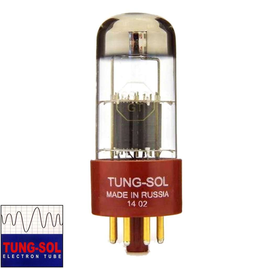
Key Characteristics of the 6SL7
The 6SL7 is a high-mu (high amplification factor) twin triode housed in an octal base. Its defining features make it an excellent voltage amplifier. According to its datasheets, it boasts an amplification factor (µ) of around 70, which is significantly higher than its medium-mu cousin, the 6SN7 (µ of 20). This high gain comes with a trade-off: a relatively high plate resistance (Rp) of approximately 44 kΩ and a lower typical plate current of about 2.3 mA .
The 6SL7-GT is a high-mu twin triode designed for use in resistance-coupled circuits as a voltage amplifier or phase inverter. — General Electric 6SL7-GT Datasheet
When implemented correctly in a circuit designed for its parameters, the 6SL7 is known for producing a warm and smooth sound, making it a favorite for the input stages of audio equipment where tonal character is paramount .
Why the 6SL7 is a Great Driver for the EL34
To drive a power tube like the EL34 to its full output, the driver stage must provide sufficient voltage swing. The 6SL7';s high amplification factor makes it perfectly suited for this task. A single 6SL7 triode section can easily take a standard line-level signal (around 1-2V) and amplify it to the ~20-40V peak-to-peak signal required at the EL34's control grid.
Furthermore, the 6SL7 exhibits excellent linearity, which ensures that the signal passed to the power stage is a clean, uncolored replica of the input, preserving the integrity of the music before the final power amplification and its associated harmonic coloration.
The Powerhouse: The Iconic EL34 Pentode
The EL34 is arguably one of the most famous power tubes in audio history. It is a pentode, meaning it has three grids (control, screen, and suppressor), which gives it high power sensitivity and efficiency.
The "British Sound" Embodied
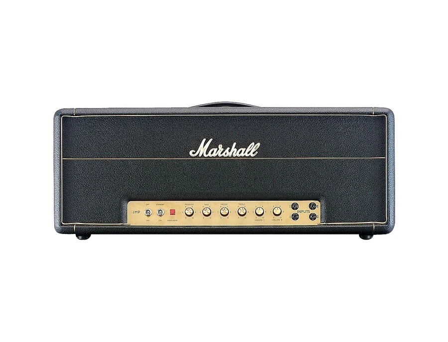
The EL34 is the cornerstone of the ";British Sound." It powered legendary amplifiers from manufacturers like Marshall and Orange, shaping the sound of rock music from the 1960s onwards. Its sonic signature is often described as aggressive and forward, with a rich midrange and excellent headroom that allows for blistering, dynamic performances .
This character—a powerful and articulate voice—makes it not only a giant in the guitar world but also a compelling choice for high-fidelity audio, where it can deliver music with authority and presence.
Operating the EL34 in a Single-Ended Configuration
While most famous for its use in push-pull circuits, the EL34 performs exceptionally well in a single-ended Class A design. In this topology, the entire signal is handled by one tube, biased to be constantly conducting. This requires careful management of its operating point to avoid exceeding its maximum plate dissipation, which is typically rated at 25 watts .
A key design choice is whether to run the EL34 in pentode mode or triode mode (by connecting the screen grid to the plate).
- Pentode Mode: Delivers higher power output and efficiency, retaining the classic, punchy pentode character.
- Triode Mode: Results in lower power output, lower distortion, and a lower output impedance, leading to a sound that is often described as smoother and more refined.
Designing the Amplifier Circuit: Key Considerations
Building a stable and great-sounding amplifier requires careful attention to the operating points of each stage and the selection of key components like the output transformer.
The Driver Stage: Setting the 6SL7's Operating Point
The operating point, or Quiescent point (Q-point), defines the tube';s idle state. A well-chosen Q-point ensures the tube operates in its most linear region, minimizing distortion. A typical operating point for a 6SL7 in a preamp stage, derived from datasheets, is:
- Plate Voltage (Ua): 250V
- Grid Voltage (Ug): -2V
- Plate Current (Ia): 2.3mA
To achieve this, a cathode resistor (Rk) is used to create the negative grid bias. Using Ohm's law (R = V/I), the cathode resistor would be 2V / 2.3mA ≈ 870Ω (a standard 820Ω or 910Ω resistor would work well). The plate load resistor (Rp) is chosen to set the plate voltage, typically in the range of 47kΩ to 100kΩ for this tube.
The Power Stage: Biasing the EL34
For an SE Class A amplifier, the tube idles at its maximum dissipation. The goal is to set an idle current that is high enough for Class A operation without exceeding the 25W plate dissipation limit. For example, with a plate voltage of 350V, the maximum idle current would be I = P/V = 25W / 350V ≈ 71mA. A safe and common practice is to idle at around 70-90% of max dissipation.
Let's choose a conservative idle point:
- Plate Voltage (Va): 350V
- Plate Current (Ia): 60mA
The Output Transformer: The Critical Link
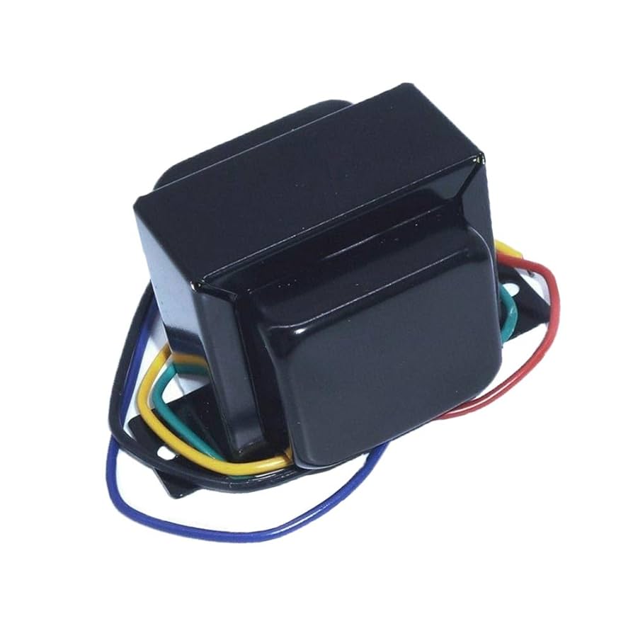
The output transformer (OPT) is perhaps the most critical component in a tube amplifier. Its functions are twofold:
- It matches the high output impedance of the EL34 (several kΩ) to the low impedance of a loudspeaker (typically 4Ω or 8Ω).
- It isolates the high DC voltage on the tube's plate from the speaker.
For a single-ended amplifier, the OPT must have an air-gapped core. This gap prevents the transformer's core from saturating due to the constant DC idle current flowing through its primary winding. For an SE EL34, a primary impedance (Z_p) of 3.5kΩ to 5kΩ is typical.
Visualizing Performance: Plate Curves and Load Lines
To truly understand how the power stage will behave, engineers use plate characteristic curves and load lines. A plate curve graph plots plate current (Ip) versus plate voltage (Vp) for various fixed control grid voltages (Vg). The load line is a line drawn on this graph that represents the load presented by the output transformer. The slope of the load line is equal to -1/Z_p.
The intersection of the load line with the different grid voltage curves shows the path the tube's operation will follow as the input signal swings. The Q-point (our idle state) sits on this line. The chart below illustrates a typical set of plate curves for an EL34 with a 4kΩ load line originating from a 400V power supply (B+). The safe operating area is also shown, bounded by the 25W max plate dissipation curve.
The Sonic Signature: What to Expect
So, what does this amplifier sound like? The final sound is a beautiful synergy of its parts. The 6SL7 provides a clean, warm, and detailed signal to the power stage. The EL34, operating in Class A, takes this signal and imbues it with its characteristic richness and authority. The single-ended topology adds a layer of second-order harmonic distortion that is inherently musical, creating a sound that is lush, three-dimensional, and engaging.
You can expect a powerful bass response, a detailed and articulate midrange where the EL34 truly shines, and clear, extended highs. For Hi-Fi listening, it will present music with a sense of realism and emotional weight. For a guitar amplifier, it will offer a touch-sensitive response, transitioning from clean tones to a sweet, singing overdrive as you dig in—the hallmark of a great single-ended design .
Conclusion: A Timeless Combination for the Modern Builder
The 6SL7-driven EL34 single-ended amplifier is more than just an electronics project; it';s an exploration into the art of sound reproduction. It combines a high-gain, linear driver with a powerful and characterful output tube in a topology celebrated for its sonic purity. While it may not be the most efficient design in terms of power consumption, its reward is a sound that is deeply musical and satisfying.
For the modern DIY audio enthusiast, this classic pairing offers a direct connection to the golden age of tube amplification, resulting in a piece of equipment that is as rewarding to build as it is to listen to.


